Continue to Site

Welcome to EDAboard.com

Welcome to our site! EDAboard.com is an international Electronics Discussion Forum focused on EDA software, circuits, schematics, books, theory, papers, asic, pld, 8051, DSP, Network, RF, Analog Design, PCB, Service Manuals... and a whole lot more! To participate you need to register. Registration is free. Click here to register now.

Want to know operation of this Schematic

Status
Not open for further replies.

sr_raval

Advanced Member level 4
Joined
Jul 23, 2009
Messages
115
Helped
0
Reputation
0
Reaction score
0
Trophy points
1,296
Activity points
2,283
Hello Everyone,

I would like to develop one charge pump relay drive circuit for boiler control, i would like to control that charge pump relay drive circuit with the microcontroller, its a basic requirement to get UL 353 and UL 1998 standard. Can anybody help me to develop this circuit.
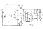
Furthermore, here i am attaching one circuit, please let me know the circuit operation. i would like to know how thic circuit operates?
 

Attachments

  • image.png
    image.png
    35.8 KB · Views: 368

Dear sr_raval
Hi
It is pretty simple . are you familiar with basic operation of opamp ? if yes where is the problem ? it is enough to know that when you get the command signal to your opto coupler the inverting input will be grounded . i think you can continue ?
Best Wishes
Goldsmith
 

Dear Goldsmith,

I am not expert in opamp, can you please elaborate how this circuit can work? its a circuit of H bridge?
 

No problem .
Why H bridge ? of course it is not ! do you know what is H bridge exactly and why we will call that H bridge ?
Anywhere , if inverting input be grounded , the out put of opamp will be +vcc (A1) . and then T2 will conduct , and then .... can't you continue ? ( just consider when we have an opmp or without feedback , it will work at comparison mode . if inverting input be higher than non inverting , thus the out put will be -vcc and vice versa . you understand ?

- - - Updated - - -

By the way i think your circuit has some errors . for example in out put transistors ( relay and freewheeling diode and that LED . isn't it ?)
 

Seems like a patent document drawing. Why don't you quote the document number so others can read the description?

To determine the circuit operation, it's necessary to know all timing parameters, to understand it's operation related to the said safety standards, you need to know the exact requirements. In so far, the question not "pretty simple". I don't know the details and thus don't want to guess about it.
 

Dear FvM
Hi
I think there is some errors in this circuit , ( out put section ) . isn't it ? hence i think you are right and he should attach the complete document .
Best Regards
Goldsmith
 

Schematics in a patent document are illustrating a principle and not necessarily correct in all details. There's obviously a missing connection knot, that's trivial.

In addition, schottky diode symbols are used to designate z-diodes.
 

Thanks Everyone,

Yes i found this circuit on one patent, actually my main goal is to develop a charge pump relay drive circuit which can certify UL standard, here i am attaching one more schematic of this, other then that i do not have any document, actually i was unable to download that patent so i have copied pictures and text also. have a look on attached docs.

- - - Updated - - -

Actually whats the purpose of this circuit?

Yes FVM you are right thats just the principle circuit so i am not stuck with this perticular circuit, but i would like to know how this circuit exactly works? Why they have used A2 comparator?
 

Attachments

  • fig2.bmp
    5.1 MB · Views: 138
  • 20120311225618kmznbafj.doc
    50.5 KB · Views: 120

1. I have been asking for the document number.
2. The circuit operation is understandable in a broad sense, requiring a square wave signal with certain parameters to activate the output. Personally I'm not motivated to track the circuit operation down without knowing the exact safety standard requirements.
 

Dear FVM,

I am not sure about the document number but i found this number 80 35733 on the word file which i have recently upload in my previous post, you can also guide me another way to design charge pump relay drive circuit operated by microcontroller.

- - - Updated - - -

Awaiting for your response friends
 

Hello Guys,

Please help me on this, do let me know if you require any other information from my side?

Thanks in advance
 

I'm missing an exact specification of required circuit function according to the related safety rules.
 

Well following are the condition where relay should not operate

1) when microcontroller fails
2) When microcontroller I/O pin goes in continous high stage
3) When microcontroller software gone hang or something wrong with software
4) when short circuit happen in relay drive section or related parts

Actually i got the information from UL that if we can control the relay with the help of charge pump concept we can satisfy above conditions, but i dont know how to develop a charge pump relay drive circuit.

Its not necessary that i have to implement this circuit with the discreate component only, I am flexible if we can develop this circuit by any of the integrated circuits also.

Do let me know if you require any other information from my side.

Thanks,
Samir
 

The problem is with the vague points 3 and 4.

- Some software errors may result in a pulsating control signal. Obviously it can't be detected, if it's timing is similar to the original output signal. But which signals can be accepted? What are the criteria.

- Failure e.g. of transistor T4 can't be detected/bypassed by the present circuit, I think. (Or didn't yet get the operation principle) Which circuit parts are assumed less reliable than the transistor and why?
 

Actually for the 3rd point we can implement bootloader and resolve that problem, and that circuit is not a ideal one, you can suggest me alternate circuit which satisfied those criteria.
You can also suggest me a alternate IC, if you know any which can serve this criteria.
I assume that now you clear about what I'm looking for?
Thanks,
Samir
 

Guys,

I am waiting for your response, please help me out
 

I believe the schematic in post #1 is a method to make a relay energize after pulses have been coming in at the left after a certain amount of time, and then make the relay open after pulses have stopped for a certain amount of time.

The pulses come from a small signal source. Hence the optocoupler. The relay coil must need more current than the small signal source can provide. The relay coil may be rated for mains level voltage.

The middle section appears to turn two transistors alternately turn on and off, to develop a charge on the capacitors at nodes X and Y.

This builds a voltage differential at the top and bottom supply rails at the right. Eventually it is great enough to provide power to the section labelled 'comparator', and the relay turns on.

When the pulses stop coming from the left, the capacitors lose their charge gradually, and the relay coil is de-energized.

I could be wrong.
 

Thanks Bradtherad,

Those information really helps me, is it a circuit of charge pump relay drive circuit?

Samir

- - - Updated - - -

Thanks Bradtherad,

Those information really helps me, is it a circuit of charge pump relay drive circuit?

Samir
 

The document you posted looks like it describes the operation of the circuit? I searched it for A2 and found: "A voltage comparator circuit R10, R11, R12, R13, DZ3, A2 is connected across the pump diodes Dl, D2 and senses the mean input voltage via the integrator R9, C3."
 

Yes my my question is is that a circuit of charge pump relay driver ?
 

Status
Not open for further replies.

Similar threads

Part and Inventory Search

Welcome to EDABoard.com

Sponsor

Back
Top