Continue to Site

Welcome to EDAboard.com

Welcome to our site! EDAboard.com is an international Electronics Discussion Forum focused on EDA software, circuits, schematics, books, theory, papers, asic, pld, 8051, DSP, Network, RF, Analog Design, PCB, Service Manuals... and a whole lot more! To participate you need to register. Registration is free. Click here to register now.

LC Low pass filter design for SPWM filtering

Status
Not open for further replies.

basofias

Junior Member level 2
Joined
Apr 14, 2009
Messages
22
Helped
1
Reputation
2
Reaction score
2
Trophy points
1,283
Activity points
1,498
Hello friends,

I am building at now, a DC-AC sinewave inverter.

I'm designing de output stage, H-bridge and LPF (Low Pass Filter), i have some questions abou te LC output filter.

My SPWM switching frequency is arround 8kHz (10kHz max)

My output sinewave are fundamental frequency 50Hz.

How can i design a LPF filter based on L section LC filter 1 pole?

Which the cutoff frequency value should I use in the calculation of the filter?

Which the attenuation value shoul i use in the same calculation? 3dB?

Which the values of typical output impedance?


Basofias!

:roll::roll::roll::roll::roll::roll::roll::roll:
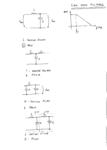
 

section LC filter 1 pole?
Dear basofias
Hi
When you say LC filter , and you don't use current loop , you have two pole not one pole .
Anywhere , you should use a butterworth filter ( 2nd order ) . and becasue you used SPWM , you can use an LPF with f0=4KHZ ( because your lowest frequency is 50HZ) .
BTW : don't forget to add a feedback loop to stabilize your out put voltage , because you will use a butter worth filter , and if your load become higher than normalized load of your filter the out put voltage can be as high as some KV !
Best Wishes
Goldsmith
 

goldsmith can you explain how to cater for the output voltage in the design of the low pass filter.

and also do you mean that f0 is the cutoff frequency
 

Dear babatundeawe
Hi
About f0 , yeah , my mean is cut off frequency . but what do you mean by this :
how to cater for the output voltage in the design of the low pass filter.
Best Wishes
Goldsmith
 

Hello friends,

About your expalnation, I am understanding it!

Why you choose 4kHz for fc? It's not possible to use onother value of frequency?

Please see the attached picture, for better understanding of my questions.

example3.png

Thanks.


Basofias
 

Dear basofias
Hi again
A question about the diagram that you made : do you know meaning behind pole ? if yes , do you know that the number of poles of each circuit is depends on what ?
You wrote one pole , nearby some of your filters .
Do you know meaning behind order of each filter ? if no , i can describe all of them for you . ( i think your assumption isn't correct ) .
I selected 4 kHZ because , you need 50 HZ at your out put !!! did you confused about this ? as you probably know , if you try to achieve a sine wave from a 50HZ square wave , it will be very hard and expensive . and we won't use that way , ( never ) .
As you perhaps , know , each SPWM consists a low frequency component and a high frequency component ( with many side bands ) .
The lowest frequency that you have in the spectrum of your SPWM is 50HZ , so the cut off frequency , can be higher than this , when your carrier frequency is high ! thus the value of elements of your filter will be reasonable , and it will be cheap !
Best Events
Goldsmith
 
Last edited:

Hello Goldsmith,

I think 2 pole filter is equal to socond order filter, for that i say this in my diagram.

I wrote 1 pole in all the filters, except in the last one, because I think that these filters only have one order and one pole!

Not exists relantionship of these two parameters??? Number of poles and order number?

My idea is not correct????

Well, my spwm signal consists in a 50Hz PWM and High frequency PWM for switching the low side FET's of the H-Bridge.

My High frequency PWM is arround 8kHz, and I understand, that my fc can be higher than 50Hz, but why 4kHz? Its possible 2kHz for example?

The idea is make low pass filter with ressonable type elements one inductor and one capacitor only, and it will be cheap! exactly!

I have posted some questins about SPWM, but in other thread of tis forum.

See the link please:

https://www.edaboard.com/threads/250505/

Thanks for the help my friend!

Basofias
 

I think 2 pole filter is equal to socond order filter....
Yes.

The idea is make low pass filter with ressonable type elements one inductor and one capacitor only....
That is a second order filter. It should be enough.

My High frequency PWM is arround 8kHz, and I understand, that my fc can be higher than 50Hz, but why 4kHz?
I think 4KHz is too high. 1 KHz would be better, or maybe even 500Hz. The filter cutoff frequency must be low enough to give good attenuation at 8KHz.
 

Hi again
I wrote 1 pole in all the filters, except in the last one, because I think that these filters only have one order and one pole!
When you have an inductor and a capacitor , you have a 2nd order filter . and when you have 3 imaginary elements , it means that you have three pole , and it will be 3rd order .
Not exists relantionship of these two parameters??? Number of poles and order number?
The number of poles will select the order of each filter .
And about Cut of frequency , 2kHZ seems ok , but the value of elements of your filter will be higher . with an approximation , we can select it by 1/2FC
Best Luck
Goldsmith
 

gold smith,

i meant that how do we factor in the values of the coils of the inductor in other to be able to handle the required voltage say like 230v ac.

and also pls i will like to educate me more on low pass filter i m a bit confused as per wat u explaining in regards to the fact that i need to allow low frequency to pass and yet i have cuttof frequency that is still high. like what you are explaining to basofias.

thanks
 

i meant that how do we factor in the values of the coils of the inductor in other to be able to handle the required voltage say like 230v ac.
Dear babatundeawe
Hi
What do you mean by that ? your words confused me ! i know that you have a question in your mind . but how can i answer it when i couldn't understand your accurate meaning ? if you simplify your mean and describe it , perhaps i can help you .
And about low pass filters , there isn't any problem , from my side ! just tell where is your problem on them , i can describe the behavior of them , in detail .
Best Wishes
Goldsmith
 
Dear Goldsmith

thanks for your patience and the enthusiasm to help. i will try and break my need down as close as possible.

i am trying to build an iverter using the sg3525 to drive a ferrite in push pul configuration and generate a voltage of 325 dcv at 5khz. then i am going to use pic to generate sinewave in fullbridge mode at about 5khz.

so my question is this, definitely i know i need a lowpass filter to bring the frequency down to my fundamental frequency of 50hz

1. how can i achieve this, considering
a. output power (in the range of 1000w and more)
b.output current. (from 5amps)
c. output voltage. (230 ACV)

2. what type of filter will i need. (an LC or an RC) cos i know its difficult to make an inductor if u dont have an inductance meter.

thanks
babatundeawe
 

Hello babatundeawe,

How do you do sinewave with PIC micro? Three level PWM? Or Bilevel PWM?

About your questions:

Fcutout = 2,5kHz
Filter LC type

The ressonant elements Inductor with rating for 5A and capacitor X2 type.

I have only one question in these filters... which the characteristic impedance for this type of situation 10ohm, 20ohm, 50ohm ???

I hope to have helped in your questions,

Thanks
 

Dear basofias
Hi
Did you see my previous posts carefully ? as i told you about out put impedance of these filters , you can design it for very low impedances ( such as 10 ohms or less ) and then you have to take DC feed back from out put and then rectify and filter it ( the feed back voltage ) and then you should give this sample to the feed back voltage of first stage . do you know why ? or are you familiar with the behavior of butter worth filters ? ( instead of difference impedances )
Good luck
Goldsmith

---------- Post added at 15:11 ---------- Previous post was at 15:08 ----------

Dear babatundeawe
Hi
About your out put filter , you should use LC type , because of two reason :
1- higher order instead of RC filter
2- Lower dissipation
And about your other questions , can you tell me , a bit more explanations that what is your problem ?
Aren't you familiar with steps of design ? or you just can't select the components ( mosfets or IGBTs or ....etc )
Best Wishes
Goldsmith
 

Hello goldsmith,

I have understanded all your explanations, without problems!

At this moment I'm just testing the h bridge controller, and the H bridge.

My H bridge at this moment is based on 4 N-Channel Mosfets, and the supply voltage (DC BUS) is 12 or 24V, only for testing the response of the circuit and the filtering stage.

When I have a feedback of these tests I put them here.

Thanks for all help!

Best Regards!

Basofias
 

Goldsmith,
thanks for ur desire to help.

i quite know what i am trying to do but i need more clarity as per the design of what i want to do. i know how to configure the full bridge, and selecting the component that i needed but where i am having problem is the design of the low pass filter. i need to know the parameters involved in making one (LC filter) as u ve adviced.

pls can u give me a tutorial on that.

thanks

@basofias

well i dont understand the three level pwm or bilevel. but i am trying to implement this using the fullbridge capability of the pic eg 16f887.

i am going to do this by generating a sine LUT.

regards
 

Dear babatundeawe
Hi again
The problem is that i don't know that what is your exact problem in design steps of a simple LC filter ? aren't you familiar with formulas of design ?
Best Luck
Goldsmith
 

Gold smith need ur guide for the LC Circuit calculation ...for my sine wave inverter design i had success done it proteus


but one problem .. i really not understand for choosing the L and C value...for my proteus i had done it is using some knowledge for transistor , with guessing and luck to success it...i used the H-Bridge configuration depend on the BJT ..... to the spwm pulse the full cycle period is 50HZ and i use the virtual transformer to step up the voltage and in the last step i setting my component value L=8.8H the Capacitor I used C=1000nF ...i had test many type of value in my design L=9.8 also can get sine wave between 8.8H to 9.8H only available to getting sine wave.......very weird i dont know what problem for these value happen.....So just really need ur guide for understanding to choosing the value of L and C to oscillate Sine wave....... just know a little concept of the LC circuit to choose Cut off frequency..F_(cutoff frequency)=1/(2π √LC)...........

but for my own understanding maybe ....


50Hz= 1/(2π√((L)(1000nF)))
2500Hz=(1/(2π√((L)(1000nF))))^2
L=10.1H ~~

why i choose 1000nF....because tested in software really due to many condition ...if i choose 1000uF or other value....will be come out problem for the sine wave ...cannot generate pretty good sine wave......and use 1000nF to substitution ....play on it...... then i desired this such big inductance

but just wanted to ask, if i control my pulse of spwm to generate high frequency at 2KHz...actually wanna try on 5Khz ..but for my simulate cannot be handle so fast mirco pulse always due to error.....erm if i use 2KHz ... can i use concept to choosing component value ???.F_(cutoff frequency)=1/(2π √LC). , issit this concept for choosing component really available to use it in real life ??...to generate ..nice sine wave shape ...????because stay in oversea ...really no convenience to puchase and keep changing component value .......and no good technique for making inductor................if i make high frequency for the spwm....then maybe i will reduce my 10 Henry inductor value...that would be cut cost for my design. waiting for u reply ..because i had ask u in other posted but u didnt reply me hehe~~~~anyway thank for u willing to help about this...and sorry for my poor english

sorry for my all beginner question ...no pretty good on this..... i show out my result in below for the waveform what i get

**broken link removed**

Uploaded with ImageShack.us


**broken link removed**

Uploaded with ImageShack.us


hope can anyone guide on this ~~~
 

Hi Longcrystal
As you probably know best situation for an LC butter worth 2nd order filter is where zeta is one ( RO=0.5sqrt(L/C) ) . so you can easily calculate numbers according this formula and determine a parameter to normalize values . if it is not clear to you , tell me , please , then i can write some pages for you as an example !
Best Wishes
Goldsmith
 

i really not understand for choosing the L and C value

I wonder if this involves sending high current through the coil?

A small henry value does this better than a large henry value.

Then to achieve a desired frequency, you will need a larger capacitor.

You will need to wind the coil with large enough wire to handle the current.

You will need enough metal mass in the core, so it will not saturate during a cycle.

This will require tradeoffs, to achieve the power output you want.
 

Status
Not open for further replies.

Similar threads

Part and Inventory Search

Welcome to EDABoard.com

Sponsor

Back
Top