godfreyl
Advanced Member level 5
No, longcrystal still does not know what values to use or how to calculate them.And is the problem solved know ?
I know what a Butterworth filter is. Maybe you need to read more about it if you think this formula is correct:For butterwoth , you can see below :
https://en.wikipedia.org/wiki/Butterworth_filter
Or search in goodle .
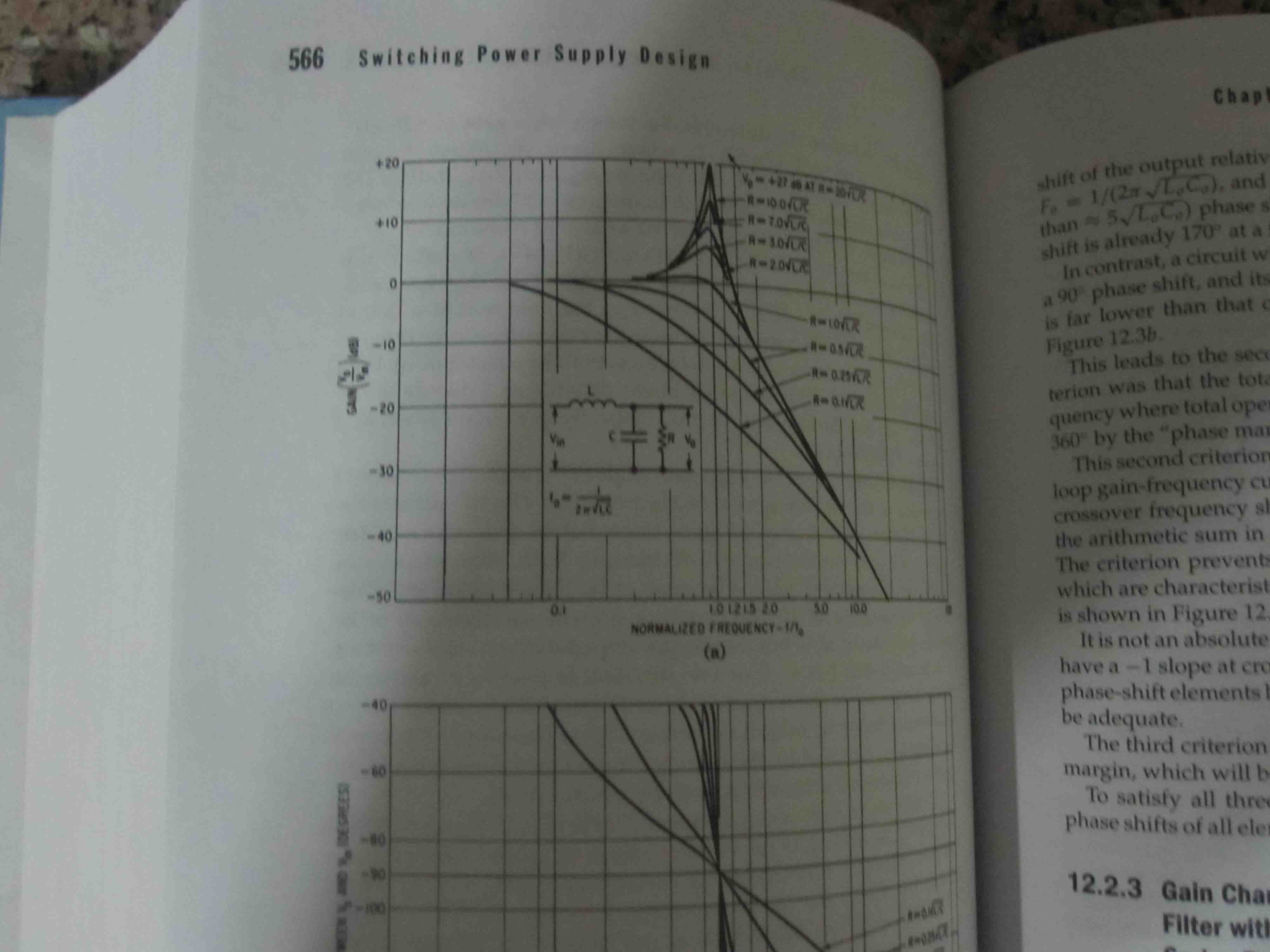
That formula is not correct for a two pole LCR Butterworth filter.RO=0.5sqrt(L/C)