Continue to Site

Welcome to EDAboard.com

Welcome to our site! EDAboard.com is an international Electronics Discussion Forum focused on EDA software, circuits, schematics, books, theory, papers, asic, pld, 8051, DSP, Network, RF, Analog Design, PCB, Service Manuals... and a whole lot more! To participate you need to register. Registration is free. Click here to register now.

Transformer secondary current - How to calculate?

Status
Not open for further replies.

shashankbr

Junior Member level 1
Joined
May 26, 2011
Messages
15
Helped
0
Reputation
0
Reaction score
0
Trophy points
1,281
Activity points
1,403
I have a step down transformer with the following ratings.

Input AC: 230 V / 50 Hz
Output AC: 18.5 V at 5.4 A

It had gone bad a few days back & I got it rewound from a local electrician.
Now when I check the output voltage which comes to 19 V (which I think is acceptable) but I am not sure how much current it is giving.

Because when I connected the transformer to a rectifier IC, the output pins of the IC got short.
And the device is not working.

Can you please tell me how can I measure the output current of transformer?
 

I think current is not the reason.
Maybe rectifier was damaged when your transformer was destroyed.
When iron core is same and secondary voltage is about same as before,
is secondary current same too.
(If winding wire diameters and coil laps are same as before. )

You can test secondary current with resistive load.
I = U / R

Nprimary / Nsecondary = Vprimary / Vsecondary = Isecondary / Iprimary

N number of laps in coil
V voltage
I current
 
Last edited:
I think current is not the reason.
Maybe rectifier was damaged when your transformer was destroyed.
When iron core is same and secondary voltage is about same as before,
is secondary current same too.

Thanks a lot. I too think that current is not a problem. As the rectifier had a current rating of upto 15 A.
I will have to replace the rectifier.
 

You should consider, that a rated transformer current of 5.4 A involves a short circuit current of may be 50 A. So the most likely szenario is, that you first shorted the DC output of your power supply, then blow the rectifier and finally the transformer. Alternatively, the rectifier died spontaneously of thermal wear without shorted output. In any case, the transformer would never being damaged with a suitable secondary fuse.
 

current is not a problem. As the rectifier had a current rating of upto 15 A.

even if your rectifier current rating is low, still you can use it but you should not connect heavy load at the rectifier o/p...
So, for a transformer, in your case 18.5V 5.4A, it doesn't means that it will always provide 5.4A ... Current depends on the load resistance..For example, for glowing an LED, it just require a current about 10 or 20 mA and it will take only that much current even if you connect it to the rectified O/P of a 3V 5A transformer or an 18.5V 5.4A transformer (provided a resistor in series with the LED)...
When you are connecting a heavy load at the transformer O/p , say, an 18.5 V 5A bulb, then it take a 5A current...
Now assume you just shorted the O/P of rectifier, then a maximum current will flow , which will be greater that the specified current rating and if it is shorted for a while, it may damage your transformer and/or rectifier.....:sad:, may be some time this may be happened to you earlier...
 

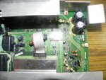
DSCN7052.jpg**broken link removed**
Now assume you just shorted the O/P of rectifier, then a maximum current will flow , which will be greater that the specified current rating and if it is shorted for a while, it may damage your transformer and/or rectifier.....:sad:, may be some time this may be happened to you earlier...

I took out the rectifier IC from the PCB and checked. It is not shorted now. But the output traces of rectifier on the PCB are shorted. Can you tell me any method to find out the short?
I think it must be most probable the two capacitors connected to the IC (4700uF, 35V) but again there is no physical damage on them?
Could it be the problem with amplifier IC - NXP's TDA8947J as it is directly connected to the output of the rectifier?

The rectifier IC is RECTRON Semiconductors - RS401L
 
Last edited:

Having a massive short in an electrolytic capacitor is unlikely, the amplifier IC sounds more reasonable.
 

Having a massive short in an electrolytic capacitor is unlikely, the amplifier IC sounds more reasonable.

Yes. But my chances of replacing that are low as the PCB is quite complicated and lot of components means lot of possibilities (There are two amplifier ICs). Can you suggest some method by which I can be sure that one of the amp ICs is gone bad? Any visual indication?
The PCB area near the amp ICs has become a little sticky. What would that suggest?
 

A simple, non-destructive method to locate shorts utilizes a lab supply and a sensitive millivoltmeter. Feed a limited current of e.g. 1 or 2 A into the shorted supply input and check the voltage drop along the PCB traces.
 
Hey all.

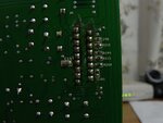
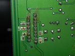
Can we infer something from these pictures?
These are the back side of the amplifier IC.
Does this mean that the IC is burnt?

DSCN7345.jpg

DSCN7339.jpg
 

Can you show the back side of shorted Area. May be it shorted while coming contact with the metal case below (If it has one).
 

Can you show the back side of shorted Area. May be it shorted while coming contact with the metal case below (If it has one).

Sorry I did not understand you. This is the solder side of the PCB showing amplifier ICs TDA8947J. Does the sticky material oozing out near it show that it may be burnt?
 

The sticky part is the protective coating which is applied to all the professional PCB's.

1. I am just asking to show the other side of the burnt area i.e. back side of your first picture.

2, Is that a computer power supply or wat?

3. was it in a metal case?
 

1. I am just asking to show the other side of the burnt area i.e. back side of your first picture.

2, Is that a computer power supply or wat?

3. was it in a metal case?

The other side is the metal casing. It is also the heat sink for the amplifier IC.
Its not computer power supply but amplifier of a home theater system.
 

What is the device in the first picture connected right above the burnt area.
how did you check the rectifier?
 

It doesn't look burnt. I rather wonder, if the amplifier has been repaired before, with desoldering the IC. There seems to be excessive flux around the IC pins. If the amplifier hasn't been repaired, overheating of the IC may have happened. But it has short circuit and overtemperature protection and should handle it.

A mistreatment, that most likely won't be tolerated by the IC is overvoltage. I see, that the suggested supply voltage is 18 V with 26 V maximum rating in operation. This means, that both 18.5 or 19 V AC is rather near to maximum rating and a grid overvoltage of e.g. 10 % could already kill the amplifier. This sounds like a pretty bad design.

You would want to remove a few windings from the transformer secondary for safe operation.
 
It doesn't look burnt.
A mistreatment, that most likely won't be tolerated by the IC is overvoltage. I see, that the suggested supply voltage is 18 V with 26 V maximum rating in operation. This means, that both 18.5 or 19 V AC is rather near to maximum rating and a grid overvoltage of e.g. 10 % could already kill the amplifier. This sounds like a pretty baddesign.
You would want to remove a few windings from the transformer secondary for safe operation.

Thank a lot FvM. That information helped a lot.

But I have still one doubt. The rectifier IC that it uses - RS401L will have a steady DC output right? Hence even if AC input to circuit is 19V rms the output Vcc to amplifier IC should not cross 26V right?

One more doubt - If at all the amplifier IC is gone, would it be wise to replace it and solder a new one at that place? Because I feel the design is quite complex with heat sink and all.

https://www.rectron.com/data_sheets/rs401l-rs407l.pdf
 

You would be having rectified output not DC. There is a difference between Rectified and DC output.
In the datasheet input voltage to your rectifier voltage can be 35V RMS so its safe for rectifier.

19VRMS = 26.87V Peak
26.87 -1 (rectifier voltage drop) =25.87V peak and your capacitor will charge upto this voltage in load condition.

So yes FvM is right that it may harm your Amplifier.

Remove some winding or put some regulator circuit in between.
 

Apparently the amplifier has been working with the present AC voltage. I mainly wanted to point to a possible reason for damage of the IC, grid overvoltage may be necessary to trigger it. It may be also the case, that the IC typically stands higher supply voltages, e.g. 30 V and more. But a designer should never rely on this kind of assumptions.

It's not proven however, that the IC is actually damaged, although I assume this as the most likely explanation. The heatsink should be a problem in changing the IC, desoldering it without damaging the board requires suitable tools.
 

Yes agreed. I was looking in to the Amplifier data sheet and found that it has protection both against high temperature and short circuit. But interesting thing is that it continue to flow the current up to its tolerance level. You can say that it limits the current on short circuit or high loads. So i think Amplifier is ok and it didn't draw enough current that shorted the board, what do you say?
 

Status
Not open for further replies.

Part and Inventory Search

Welcome to EDABoard.com

Sponsor

Back
Top