Continue to Site

Welcome to EDAboard.com

Welcome to our site! EDAboard.com is an international Electronics Discussion Forum focused on EDA software, circuits, schematics, books, theory, papers, asic, pld, 8051, DSP, Network, RF, Analog Design, PCB, Service Manuals... and a whole lot more! To participate you need to register. Registration is free. Click here to register now.

need of help for designing 8x8 led matrix

Status
Not open for further replies.

prakashvenugopal

Advanced Member level 1
Joined
Jun 1, 2011
Messages
473
Helped
15
Reputation
30
Reaction score
15
Trophy points
1,298
Activity points
4,973
hi,

can anyone tell me how to implement 8x8 led matrix using vhdl code. please help me.


thanks,
V. Prakash
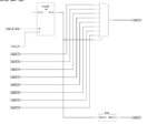
 

count to 8 - 3 bits, the decoder up to 8 lines - the choice line. and the columns give the data in accordance with the line number. This is called a dynamic display.
 

hi,

can you explain this in details.?


Thanks,
V. Prakash

---------- Post added at 15:01 ---------- Previous post was at 14:26 ----------

hi treqer,

I am in need of this vhdl code. can you please explain in details as i couldnt understand clearly?


Thanks,
 

entity disp is
Port ( main_clk : in STD_LOGIC;
displ_en_strob : in STD_LOGIC;
reg0 : in STD_LOGIC_vector(0 to 7)
reg1 : in STD_LOGIC_vector(0 to 7)
reg2 : in STD_LOGIC_vector(0 to 7)
reg3 : in STD_LOGIC_vector(0 to 7)
reg4 : in STD_LOGIC_vector(0 to 7)
reg5 : in STD_LOGIC_vector(0 to 7)
reg6 : in STD_LOGIC_vector(0 to 7)
reg7 : in STD_LOGIC_vector(0 to 7)
col : out STD_LOGIC_vector(0 to 7);
row : out STD_LOGIC_vector(0 to 7));
end disp;

architecture Behavioral of disp is

signal cnt_c : std_logic_vector(0 to 2);

begin

SM : process (main_clk)
begin
if (main_clk'event and main_clk = '1') then
if (displ_en_strob = '1') then
cnt_s <= cnt_s + 1;
end if;
end if;
end process SM;

ds : process (cnt_s)
begin

if cnt_s = "000" then
col <= "10000000";
row <= reg0;
elsif cnt_s = "001" then
col <= "01000000"; ;
row <= reg1;

-- too lazy to write--

elsif cnt_s = "111" then
col <= "00000001"; ;
row <= reg7;
end if;
end process ds;
 

8*8 means 8 rows and 8 columns.
So 3 bits for row index and 3 bits for column index.

Select the row or col using these 6 bits and make it 'high' to glow the particular led.
 

8*8 means 8 rows and 8 columns.
So 3 bits for row index and 3 bits for column index.

Select the row or col using these 6 bits and make it 'high' to glow the particular led.

if we have to work with all the LEDs rather than one, the LED current will increase to 64 times
 

hi treqer,

thanks for your code. i will check and let you know.


thanks,
V. Prakash
 

hi treqer,

I had used your code and generated the RTL Schematic for it. Please refer the attached schematic. In this code, you had used reg0 to reg7 for rows. i have to connect 64 Input for it? suppose i have to display character "A" in led array. what i have to do? Please let me know.

thanks,
V. Prakash


led_matrix.JPGledmatrix1.JPG
 

reg0 00000111
reg1 00010100
reg2 01000100
reg3 10000100
reg4 10000100
reg5 01000100
reg6 00010100
reg7 00000111


column code should be inverted-

resistors do not forget
 

hi treqer,

Thanks. now i am clear with your logic. But can you please tell me know i have to need 64 inputs to check this?
that is:
reg0 - 8 inputs
reg1 - 8 inputs
reg2 - 8 inputs
reg3 - 8 inputs
reg4 - 8 inputs
reg5 - 8 inputs
reg6 - 8 inputs
reg7 - 8 inputs.. totally 64 inputs to control this led matrix? can you please give an idea i have to check this? i have to generate an input externally that is reg0 to reg7 to display my own character? please let me know.

Thanks,
V. Prakash
 

to do character generator. He is a ROM 3-bit addresses that represent the columns. and 8 or more bits set the number of characters. controlling the number of characters you can see all the letters.
 

hi treqer,

I have to fed the data to reg0 to reg7 as follows to generate a character "A":
reg0 00000111
reg1 00010100
reg2 01000100
reg3 10000100
reg4 10000100
reg5 01000100
reg6 00010100
reg7 00000111

i am clear, if we change the reg0 to reg7, we can generate our own characters.

can you please suggest me how to check. I have to keep these register has external inputs.? or we can check this without that. can you please suggest me.

Thanks,
V. Prakash
 

You can download these registers in series use clk. with a number of conclusions will be 9

reg1<= reg0;
-------------------
reg7 <= reg6;

check when? debug on set? To test these prophetic need to turn in one of the registers to write FF AA 55. Others leave 00. So 8 times

---------- Post added at 15:01 ---------- Previous post was at 14:58 ----------

signal reg_0 : std_logic_vector(0 to 7) := "10101010";

not work in some altera

reg_0 <= "10101010";

work
 

hi treqer,

Can you please explain in details? I have to use shift register for it? Do you have the code for it?


thanks,
V. Prakash
 

shr : process (serial_clk)
begin
if (serial_clk'event and serial_clk = '0') then
reg7 <= reg7(1 to 7) & reg6(0);
reg6 <= reg6(1 to 7) & reg5(0);
reg5 <= reg5(1 to 7) & reg4(0);
---------------------------------------
reg0 <= reg0(1 to 7) & serial_data;

end if;
end process shr;
 

Hi treqer,

I had added that shift register code with the existing code. please refer this:

entity disp is
Port ( main_clk : in STD_LOGIC;
displ_en_strob : in STD_LOGIC;
serial_clk : in std_logic;
serial_data : in std_logic;
reg0 : inout STD_LOGIC_vector(0 to 7);
reg1 : inout STD_LOGIC_vector(0 to 7);
reg2 : inout STD_LOGIC_vector(0 to 7);
reg3 : inout STD_LOGIC_vector(0 to 7);
reg4 : inout STD_LOGIC_vector(0 to 7);
reg5 : inout STD_LOGIC_vector(0 to 7);
reg6 : inout STD_LOGIC_vector(0 to 7);
reg7 : inout STD_LOGIC_vector(0 to 7);
col : out STD_LOGIC_vector(0 to 7);
row : out STD_LOGIC_vector(0 to 7));
end disp;

architecture Behavioral of disp is

signal cnt_s : std_logic_vector(0 to 2);

begin

SM : process (main_clk)
begin
if (main_clk'event and main_clk = '1') then
if (displ_en_strob = '1') then
cnt_s <= cnt_s + 1;
end if;
end if;
end process SM;

ds : process (cnt_s)
begin

if cnt_s = "000" then
col <= "01111111";
row <= reg0;

elsif cnt_s = "001" then
col <= "10111111";
row <= reg1;

elsif cnt_s = "010" then
col <= "11011111";
row <= reg2;

elsif cnt_s = "011" then
col <= "11101111";
row <= reg3;

elsif cnt_s = "100" then
col <= "11110111";
row <= reg4;

elsif cnt_s = "101" then
col <= "11111011";
row <= reg5;

elsif cnt_s = "110" then
col <= "11111101";
row <= reg6;

elsif cnt_s = "111" then
col <= "11111110";
row <= reg7;
end if;

end process ds;


shr : process (serial_clk)
begin
if (serial_clk'event and serial_clk = '0') then
reg7 <= reg7(1 to 7) & reg6(0);
reg6 <= reg6(1 to 7) & reg5(0);
reg5 <= reg5(1 to 7) & reg4(0);
reg4 <= reg4(1 to 7) & reg3(0);
reg3 <= reg3(1 to 7) & reg2(0);
reg2 <= reg2(1 to 7) & reg1(0);
reg1 <= reg1(1 to 7) & reg0(0);
reg0 <= reg0(1 to 7) & serial_data;
end if;
end process shr;

end architecture Behavioral;

------
I had attached the RTL Schematic also with that. Please refer that. Now i can give the data in the serial_data input to control the row data. If suppose i have to print the Character "A". what is the data i can send in the serial input?. can you please let me know.

thanks,
V. Prakash
 

Attachments

  • rtl_schematic_led_matrix.JPG
    rtl_schematic_led_matrix.JPG
    24.1 KB · Views: 118

Hi treqer,

I had added that shift register code with the existing code. please refer this:

entity disp is
Port ( main_clk : in STD_LOGIC;
displ_en_strob : in STD_LOGIC;
serial_clk : in std_logic;
serial_data : in std_logic;
reg0 : inout STD_LOGIC_vector(0 to 7);
reg1 : inout STD_LOGIC_vector(0 to 7);
reg2 : inout STD_LOGIC_vector(0 to 7);
reg3 : inout STD_LOGIC_vector(0 to 7);
reg4 : inout STD_LOGIC_vector(0 to 7);
reg5 : inout STD_LOGIC_vector(0 to 7);
reg6 : inout STD_LOGIC_vector(0 to 7);
reg7 : inout STD_LOGIC_vector(0 to 7);
col : out STD_LOGIC_vector(0 to 7);
row : out STD_LOGIC_vector(0 to 7));
end disp;

architecture Behavioral of disp is

signal cnt_s : std_logic_vector(0 to 2);

begin

SM : process (main_clk)
begin
if (main_clk'event and main_clk = '1') then
if (displ_en_strob = '1') then
cnt_s <= cnt_s + 1;
end if;
end if;
end process SM;

ds : process (cnt_s)
begin

if cnt_s = "000" then
col <= "01111111";
row <= reg0;

elsif cnt_s = "001" then
col <= "10111111";
row <= reg1;

elsif cnt_s = "010" then
col <= "11011111";
row <= reg2;

elsif cnt_s = "011" then
col <= "11101111";
row <= reg3;

elsif cnt_s = "100" then
col <= "11110111";
row <= reg4;

elsif cnt_s = "101" then
col <= "11111011";
row <= reg5;

elsif cnt_s = "110" then
col <= "11111101";
row <= reg6;

elsif cnt_s = "111" then
col <= "11111110";
row <= reg7;
end if;

end process ds;


shr : process (serial_clk)
begin
if (serial_clk'event and serial_clk = '0') then
reg7 <= reg7(1 to 7) & reg6(0);
reg6 <= reg6(1 to 7) & reg5(0);
reg5 <= reg5(1 to 7) & reg4(0);
reg4 <= reg4(1 to 7) & reg3(0);
reg3 <= reg3(1 to 7) & reg2(0);
reg2 <= reg2(1 to 7) & reg1(0);
reg1 <= reg1(1 to 7) & reg0(0);
reg0 <= reg0(1 to 7) & serial_data;
end if;
end process shr;

end architecture Behavioral;

------
I had attached the RTL Schematic also with that. Please refer that. Now i can give the data in the serial_data input to control the row data. If suppose i have to print the Character "A". what is the data i can send in the serial input?. can you please let me know.


https://obrazki.elektroda.pl/49_1312612459.jpg


thanks,
V. Prakash
 

Attachments

  • rtl_schematic_led_matrix.JPG
    rtl_schematic_led_matrix.JPG
    24.1 KB · Views: 89

in serial input is reg0-reg1-------reg7 data serial send


reg0 00000111
reg1 00010100
reg2 01000100
reg3 10000100
reg4 10000100
reg5 01000100
reg6 00010100
reg7 00000111

0000011100010100010001001000010010000100010001000001010000000111
 

hi treqer,

thank you. I will check and let you know.


thanks,
V. Prakash

---------- Post added at 10:13 ---------- Previous post was at 09:05 ----------

hi treqer,

How to generate this serial data input to display a character "A":
serial data input:
00000111000101000100010010000100100001000100010000 01010000000111.

Please let me know.

thanks,
V. Prakash
 

Hi treqer,

Do You have any idea to fed this serial data input? Please let me know.

Thanks,
V. Prakash
 

Status
Not open for further replies.

Part and Inventory Search

Welcome to EDABoard.com

Sponsor

Back
Top