Continue to Site

Welcome to EDAboard.com

Welcome to our site! EDAboard.com is an international Electronics Discussion Forum focused on EDA software, circuits, schematics, books, theory, papers, asic, pld, 8051, DSP, Network, RF, Analog Design, PCB, Service Manuals... and a whole lot more! To participate you need to register. Registration is free. Click here to register now.

pic adc negative voltage

Status
Not open for further replies.

weichun

Newbie level 2
Joined
Aug 11, 2011
Messages
2
Helped
0
Reputation
0
Reaction score
0
Trophy points
1,281
Activity points
1,315
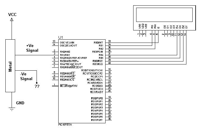
Currently, I have a metal plate which giving me voltage difference between two wire signals (Different force resulting different value). I’m trying to measure the ADC value with those two signal wires with PIC microcontroller but I’m having difficulties in obtaining the ADC value. I noticed that the conventional method of measuring ADC is to connect the +VE signal to the PIC (eg: Pin A1) with reference to the GND. But, right now I’m having two signal wires that if I’m connected one of them to the GND, it will results in constant voltage. When one of the two wires does not connected to the GND, it will gives voltage references.

Could somebody advice me on what method should I take in order to solve this matter? I believe it must be related to some signal conditioning circuit before connecting to the PIC microcontroller. Most topic discussed I’m noticed is regarding on shifting the +ve and –ve value but I don’t know if possible the theory applies here. Thanks in advanced.
 

Is your differential voltage floating or is one end fixed to somewhere? What is the range of differential voltage?

Keith.
 

The PIC will measure voltages ranging between ground (0V) and +VRef. Depending on the PIC type +Vref may be an internally generated voltage, VDD or a voltage supplied from another pin. Some PICs will also let you use a different lower (-Vref) voltage. You need to establish which configuration you are using so the range of ADC input is appropriate. What you can't do is measure a negative voltage, if a voltage lower than 0V or -Vref is fed into the PIC it could damge it.

Without seeing your schematic it's difficult to see exactly where your problem lies but in general, the rules are:

1. NO negaive voltages allowed at all on PIC pins.
2. If necessary, amplify the signal so it is a big as the ADC range (difference between +VRef and -VRef) so you get best reading resolution
3. To ensure the signal, amplified or not, never goes negaitve, apply a suitable offset to it to keep its upper and lower extremes withn +VRef and -VRef.

For example, assuming a 5V VDD and the ADC configured with -VRef = ground and +VRef = VDD, if your signal is +50mV to -50mV, amplify it by 50 times so it becomes -2.5V to +2.5V then offset it by +2.5V so it becomes 0V to 5V then feed it into the ADC. Your voltages will no doubt be different but hopefully that demonstrates the principle.

Brian.
 
Can you send us your schematic and PIC used, please?
BTW: I totally agree with Brian. This is the best way to measure ADC. set the negative value as "0V" in reference with Vreg, but you must pay attention on data sheet specs form PIC. The maximum range can't be forget.
 

Thanks for the reply, the problem I encounter is that i do not know where to connect the second signal wire since the voltage difference only exist if we directly measure the two signal with multimeter. The range of the signal value is 0.3V ~ 1.8V. Thanks. Perhaps I misunderstood Brian explanation, how would i set the offset before connecting the second wire signal to the ground.


Use an op amp differential amplifier ( or instrumentation amplifier) between the signals marked +ve and -ve. The output of the amplifier can then be connected to AN1. another way to do it is to connect +ve signal to one analog input (which you already have), connect the other (-ve signal) to another analog input of the PIC. In software, read both analog inputs and then do a subtraction. The result will be the differential voltage. Ensure GND and VCC mantioned on your schematic are the also connected to the PIC and also are within specifications.
 

hi i m not able to get the negative value of strain gauge through the ad620 to pic16f877a
how can i get the variable negative value at pic microcontroller.
 

Hijacked thread??

You can't directly measure a voltage that is negative with respect to ground with a PIC. Show us how the AD620 is wired and we might be able to help.

Brian.
 

From your schematic i understand the following:
-this metal plate is connected to gnd and vcc
-potentials measured on the metal plate can be anywhere from gnd to vcc
-interesting value is the difference between these two voltages

The simplest way (provided that neither of the voltages exceeds the range acceptable for pic) would be to measure both voltages independently and then subtract them in software. Is voltages exceed pic limits then use a precision voltage divider and then correct thing in software. In this case relation between ve+ and ve- doesn't make any difference.

The problems begin if any of those voltages can go below ground. In that case you would need an opamp circuit to shift the voltages above gnd and then divide them with voltage dividers to obtain values appropriate for pic. Some circuit protection like external clamping diodes and a resistor won't hurt either.
 

Hijacked thread??

You can't directly measure a voltage that is negative with respect to ground with a PIC. Show us how the AD620 is wired and we might be able to help.

Brian.

https://obrazki.elektroda.pl/45_1319822924.jpg
here is my schematic i got +voltage accurately but problem with negative voltage.so how can i get the negative value ???????????
thanks & regrads
 

You can't directly get a negative value. What you have to do is scale the output of the AD620 so it never goes more then 0.5 VRef. Then using a level shifter, move the zero to 0.5VRef. From maximum negative to maximum positive it will then swing from 0V to Vref, giving you maximum resolution and range. VRef is whatever you are using as the ADC reference voltage in the PIC. To return to +/- results, subtract the numeric value of 0.5VRef from the result you read.

Whatever you do, never allow a negative voltage to enter the PIC on any pin, it may be damaged.

Brian.
 

thanks
but i didnt understand can u plz send me the schematic coz i m new in electronics
 

Hi,

I will prefer in this case to use opam with negative to positive voltage conversion mechanisum....
If you need a circuit Please post me the range of your negative voltage and amplication that you want from opamp.....
with regards,

Milind
 

thanks milind my voltage range is 3.7 volt to -3 volt i dont need any amplifaction coz already used ad620 for amplifecation
i tried at lm741 but didnt get any result
regards
 

Hi Waaiz,

I am posting one circuit ...keep all the variable resistors in Kohm range and fine tune for your requirement using variable resistors......It is possible to get the derivation of the circuit using concept of virtual ground....

with regards,

Milind Opamp_range_shifting.png
 
  • Like
Reactions: waaiz

    waaiz

    Points: 2
    Helpful Answer Positive Rating
Hi Waaiz,,,

Be careful while using it with your sensor.....first try simulation or test circuit....Because .....I had used the same circuit with one of my sensor .....but it was appers to have loading and distortion effect on the sensor....as generally sensor that come with very high impedenace and very small drift in input bias current creats lot of change on the sensor performance....at least I had see this PH value measurement problem....My sencond thought is if you are facing that problem ....Probably you need to use Non-Inverting Amplifier Configuration of the Opamp....Bcz it have comparatively Low loading effects....

with regards,

Milind
 
hi milind
i have used the diffrential opamp working will in simulation.i used non inverting amplifier but now i will check in hardware hope it,s will work and after result i will tell u
thanks & regards
 

Status
Not open for further replies.

Similar threads

Part and Inventory Search

Welcome to EDABoard.com

Sponsor

Back
Top