Continue to Site

Welcome to EDAboard.com

Welcome to our site! EDAboard.com is an international Electronics Discussion Forum focused on EDA software, circuits, schematics, books, theory, papers, asic, pld, 8051, DSP, Network, RF, Analog Design, PCB, Service Manuals... and a whole lot more! To participate you need to register. Registration is free. Click here to register now.

Need Help on how to build 7 - Segment Display circuit with Series of LED's

Status
Not open for further replies.

barbaro

Member level 3
Joined
Jun 20, 2011
Messages
57
Helped
0
Reputation
0
Reaction score
0
Trophy points
1,286
Activity points
1,734
Hi there,

I'm a beginner and wanted to build a circuit that can count 2-digits up/down using the follwing:

- 2 digit (3" 7-seg using 3 LED's per seg - in series connection) So, 21 LEDs all together in 1 7-Segment display
- using a 9V power supply (is this possible?)

Please let me know if how I can utilize or connect the following ic's;

- 74HC163 (Up/Down Resettable Sync counter)
- 74LS47 (Drive/Decoder)

What else do I need aside from transistors? and how can I connect them together?

Can someone direct me or show me a schematic and do I need a swith to make it work?

Any HELP is much appreciated
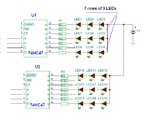
 

The '163, 'LS163A, and 'HC163 are 4-bit binary counters. For your application you need decade counters, example: '160, '162, 'LS160, 'HC162.
http://www.datasheetcatalog.org/datasheet/SGSThomsonMicroelectronics/mXurvsq.pdf

---------- Post added at 17:38 ---------- Previous post was at 17:27 ----------

Also for the UP/DOWN application you may use a CD4510
**broken link removed**
I gave you an example here:
https://www.edaboard.com/threads/216228/#post916482
(Single digit, standard LEDs, it’s not so complicated to extend for two digits and more LEDs)
 

Hi mister_rf,

Thanks again...
- my 3 LED's per segment connection is a SERIES type, is that matter?
- Should I use a Common Anode or Common Cathode connection?
- Also, do I need a uController to swithch it on?
 

Question: do you already have the counters?

If you use standard LEDs you can connect in both ways :grin: , here you can see some details
 

Attachments

  • LEDs in series.GIF
    LEDs in series.GIF
    17.4 KB · Views: 476

Hello mister_rf...

So, with all your recommendation, here's what I understand;

- OK to use the (own build) 3- LED per segment display in "series" connection.
- use C4510 Counter or HEF4510B
- use 74LS47 Display driver/decoder
- 9V power supply

Is there a switch I could use or do I need uController?

---------- Post added at 13:12 ---------- Previous post was at 13:05 ----------

mister_rf

I use 3mm standard LEDs

So, with your attachment, I can use; 74HC47 instead of the 74LS47 then, I can connect with my counter CD4510.
 

No controller needed. :grin:
What's the color for LEDs?
 

It's a red 3mm LED.

So, If i don't need a controller, could you help me design the schematic diagram then with the proper connections? I'm building a simple "SCORE BOARD" that can only count up to two digits. with a push botton to count "ones" Up and down counts. So, I will label the botton with a (+) to count up and (-) to count down. Two digit on left side of the score borad and two on the right.

- using C4510 Counter and 74LS47 Display driver/decoder
- 9V power supply
- 3 LED per segment (series connection)

What switch do I need? or I don't need it?

Please and thank you.
 

So you need also a manual pulse generator, but one of the problems with is that any mechanical pushbutton exhibits a phenomenon known as "contact bounce." To prevent this and obtain single digital pulses, we need to include with the switch a digital circuit that will react to the first contact closure, but will ignore subsequent contact bounce . We therefore may simply use a CD4093 Schmitt NAND gates, a resistor and a capacitor.
 

You asked the question "do I need a microcontroller" two times..
If you want to use a uC for this, then you can use, then don't consider it just for switching... Instead, a single uC can replace those drivers, counters etc...But the total cost may increase...(about 3 times). So, in this case ,better not to use a microcontroller.

Any way, just look this circuit to get some idea.
Then you can modify it according to your need.
303-e9a244d7fe.gif
 
One version for 2 digits counter
 

Attachments

  • counter CD4510 v1.GIF
    counter CD4510 v1.GIF
    49.1 KB · Views: 356
Hi vinosatanur,

Thanks, this is also helpful.

So, to make it work, I can simply use NE555 (or CD4093 Schmitt NAND gates), a counter 74LS192 or C4510 and a driver/decoder 74LS47 and cascade this for a 2 digit requirement each side? as I mentioned earlier, I need 2 digit counter on the left and 2 digit on the right with up/down (+/-) switches on the bottom?

Please advise.

Thanks.
 

A more complete version, to include a RESET button and two dedicated buttons, one for UP and one for DOWN.
 

Attachments

  • counter CD4510 v2.GIF
    counter CD4510 v2.GIF
    52.4 KB · Views: 526
mister_rf

Thanks a lot...

the attached One version - for 2 digits counter
is really HELPFUL.
 

Check also the second version, it's more simple to operate. :grin:

---------- Post added at 21:07 ---------- Previous post was at 20:58 ----------

By the way, you need to do some tests in order to choose the right value for the LEDs resistors (R1 to R14). Put 3 LEDs in series with some resistors, starting from 150 ohm down to 82-100 ohms, use a 9V power supply and check the intensity for the LEDs. A normal LED need 15-20mA to operate. Choose to use the resistor witch give you the most appropriate value.
 

mister_rf

Thanks...yes, the diagram its more simpler.

One more question: I see, looks like I will need - 4 NAND gates then? I appreciate any comments.
 

The CD4093B consists of four 2-input NAND Schmitt-trigger circuits.
So in this case you need only one circuit.
 

miser-rf

Thanks. I will do some testing but, first I'll find the parts list.

- I have the LEDs (3mm red)
- I will get some resistors - 150oms for R1-R14
- I need the CD4093B NAND gates
- 9V power supply (which I already have)
- CD4510 counter
- 74LS47 driver/decoder (which I already have)
- R15-R17 100K ohms resistors

did I missed any parts? please let me know...

Thanks a lot
Please let me know if
 

DIY 2 digits counter:
1 pcs CD4093
2 pcs CD4510
2 pcs 74HC47
42 pcs red LEDs
3 pcs 100k resistors
14 pcs 100 up to 150 ohms resistors
3 pcs push buttons
and don't forget, some decoupling capacitors, a common arrangement is ~100 nF ceramic/multilayer per logic IC
5 pcs 100nF
 

mister-rf

where will I connect the - "some decoupling capacitors, a common arrangement is ~100 nF ceramic/multilayer per logic IC" ?
 

Status
Not open for further replies.

Part and Inventory Search

Welcome to EDABoard.com

Sponsor

Back
Top