Continue to Site

Welcome to EDAboard.com

Welcome to our site! EDAboard.com is an international Electronics Discussion Forum focused on EDA software, circuits, schematics, books, theory, papers, asic, pld, 8051, DSP, Network, RF, Analog Design, PCB, Service Manuals... and a whole lot more! To participate you need to register. Registration is free. Click here to register now.

Brushless dc card and questions

Status
Not open for further replies.

jmx66

Member level 5
Joined
Nov 16, 2010
Messages
93
Helped
0
Reputation
0
Reaction score
1
Trophy points
1,288
Location
France
Activity points
2,045
Hi all,

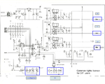
Found this brushless dc card and I only want to know use of :

- L1
- L2
- L3

I think it's related about EMI , but is there a " rule of thumb " , in order to give right values for a 1500 W , 6 step brushless dc motor?

Identical query about blue rectangle RC ?

Any links to understand these two circuits?


Thanks a lot.

jm
 

Attachments

  • numérisation0003-modif-1.png
    numérisation0003-modif-1.png
    1.1 MB · Views: 118

Your motor is driven by pulses of current. The "DC bus" is the voltage behind the current, ~1.5 X line voltage, two big capacitors to make sure its good DC. The current taken by the motor is monitored by R36, that other block is a filtering network to allow the compensation to be applied as fast as possible without any over shoot in the motors position. L1->3, make sure that any stray capacity on the leads to the motor do not over dissipate the driving transistors. At the driving frequency should limit the current to , say 2X that of the motors nominal current?
Frank
 
  • Like
Reactions: jmx66

    jmx66

    Points: 2
    Helpful Answer Positive Rating
Hi all,

Maybe something about use of L1 L2 and L3

**broken link removed**

Mook Johnson wrote:

Gents,

I'm looking at ways to bullet proof a motor driver. I'm using the standard triple half bridge configuration and want to protect against the motor phases shorting to each other or to the case (HV return). Driver is 600V bus at 1.25amps (~ 1HP).

I'm using 1200V 15 amp IGBTs for this and have a current sense resistor in each of the three legs and the HV return on the driver. These signals are monitored by the controller IC and turns off the gates if a current threhold is exceeded.

There is some propogation delay (~10uS) between when the current spike is generated across the sense resistor and when the gates actually turn off. The current in the IGBTs goes very high for this period of time.

I'm thinking of adding some local current sense resistors to the emitter of the 3 high side IGBTs and connecting a npn transistor to is such that it shorts out the gate drive immediately on a overcurrent condition ( npn NPN base and emitter across the sense resistor and the collector to the gate)

This that this would cause the IBGT to limit the current for the 10uS until the logic can shut it off.

This current limit (~5A) would be set in the SOA for the IBGT with 600V applied and the current steering diodes (already present) would prevent reverse current flow through the high side sense resistors.

See ascii sketch attempt below.

Any gottchas in doing this?


600V
____
|
|C
G /
/\/\----| <--High Side IGBT
c| \
\ b |E
npn|---|
/ \
e| /
| \
| /
-----|
|-------------- Motor phase
V
to low side IGBT


Won't that just force the IGBTs into the linear region and result in huge dissipation?

Firstly speed up your control circuitry. 10uS is a bit sluggish. You should be able to get down to 100nS without any real effort and much quicker if you really try. Then put an inductor in each output line which will limit the rate of current rise to below your circuitry protection time delay. That's the way I've always done it and it works well.

--
Gibbo


Jm
 

Status
Not open for further replies.

Similar threads

Part and Inventory Search

Welcome to EDABoard.com

Sponsor

Back
Top