Continue to Site

Welcome to EDAboard.com

Welcome to our site! EDAboard.com is an international Electronics Discussion Forum focused on EDA software, circuits, schematics, books, theory, papers, asic, pld, 8051, DSP, Network, RF, Analog Design, PCB, Service Manuals... and a whole lot more! To participate you need to register. Registration is free. Click here to register now.

Help with Transimpedance amplifier

Status
Not open for further replies.

ricopt

Member level 5
Joined
Jun 8, 2010
Messages
80
Helped
0
Reputation
0
Reaction score
0
Trophy points
1,286
Activity points
1,807
anyone out there, please help me
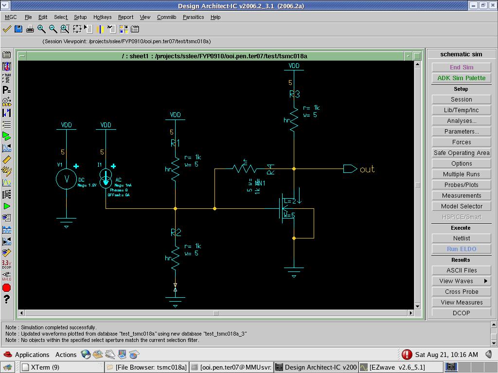
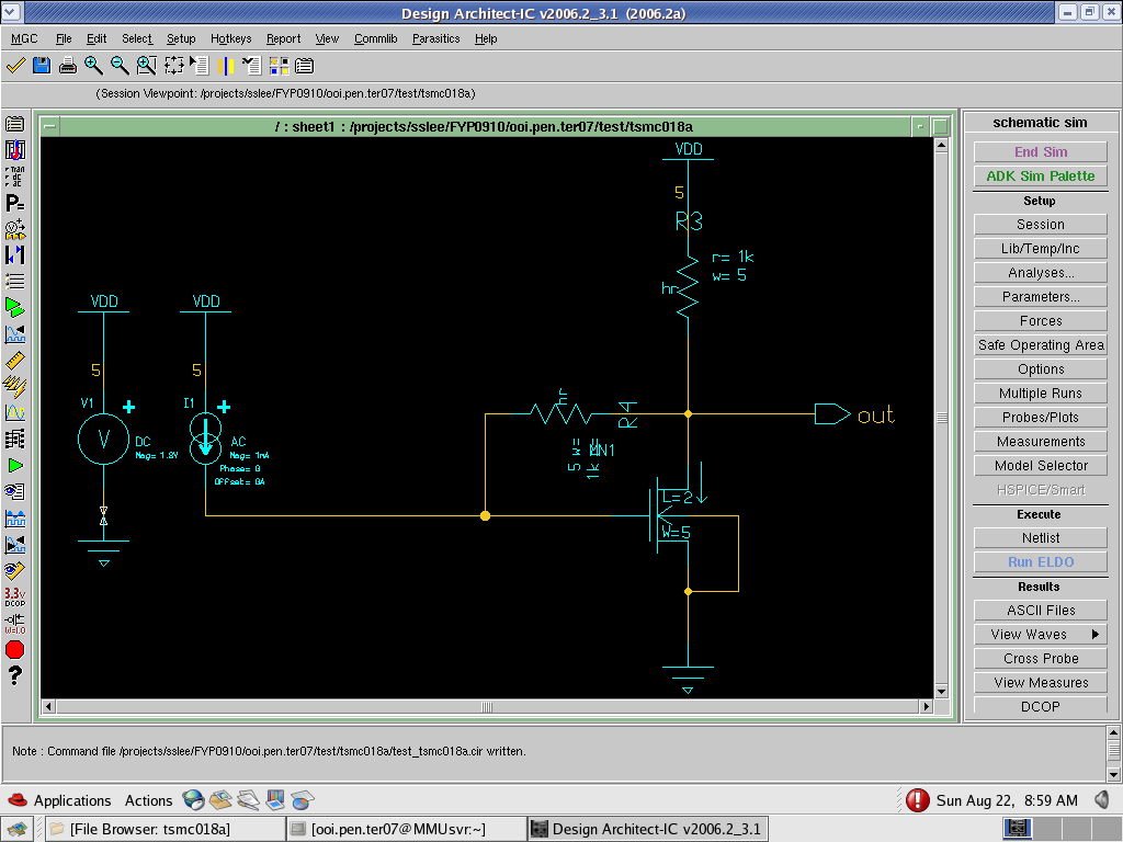
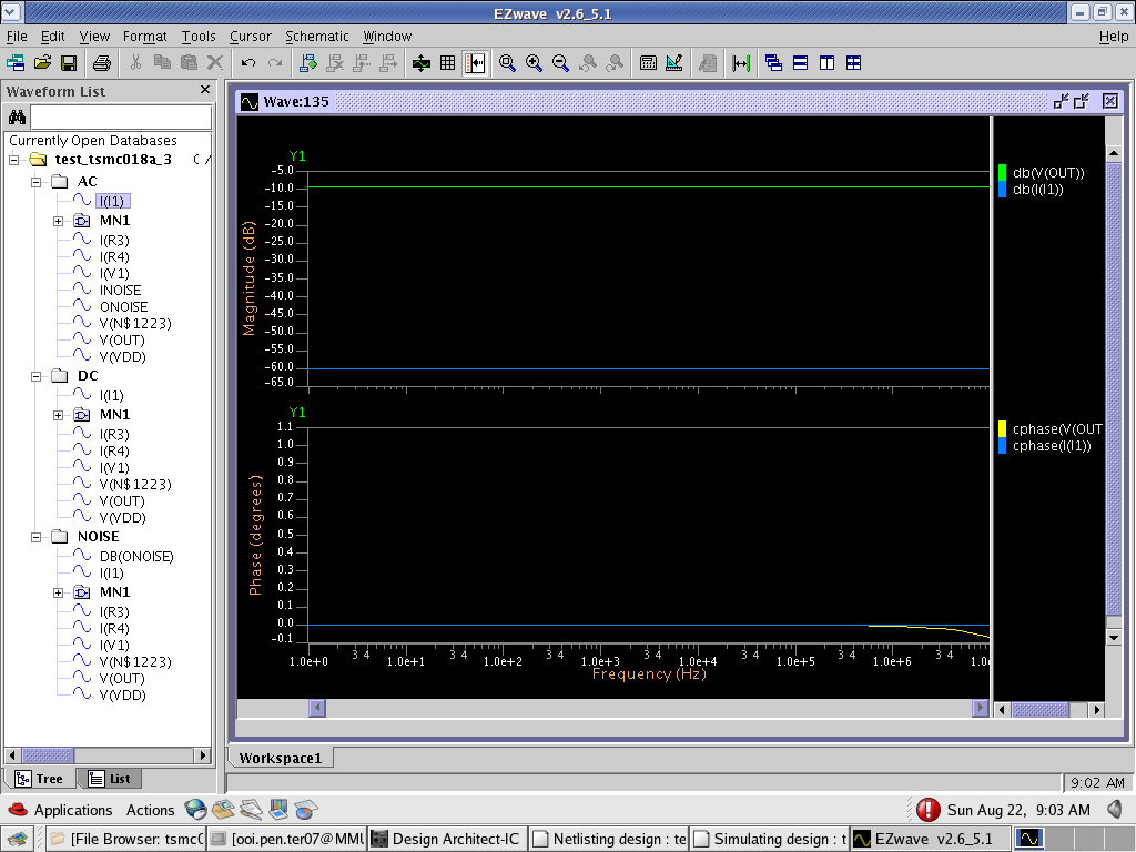
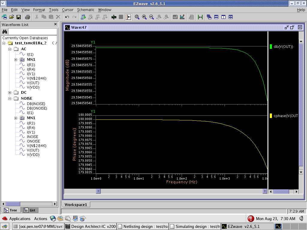
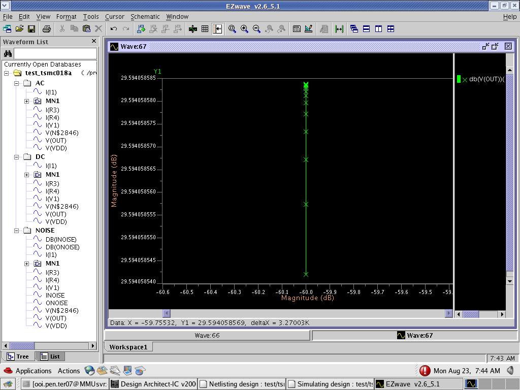
Can teach me how to prove my transimpedance amplifier is working ?
what input should i insert ?
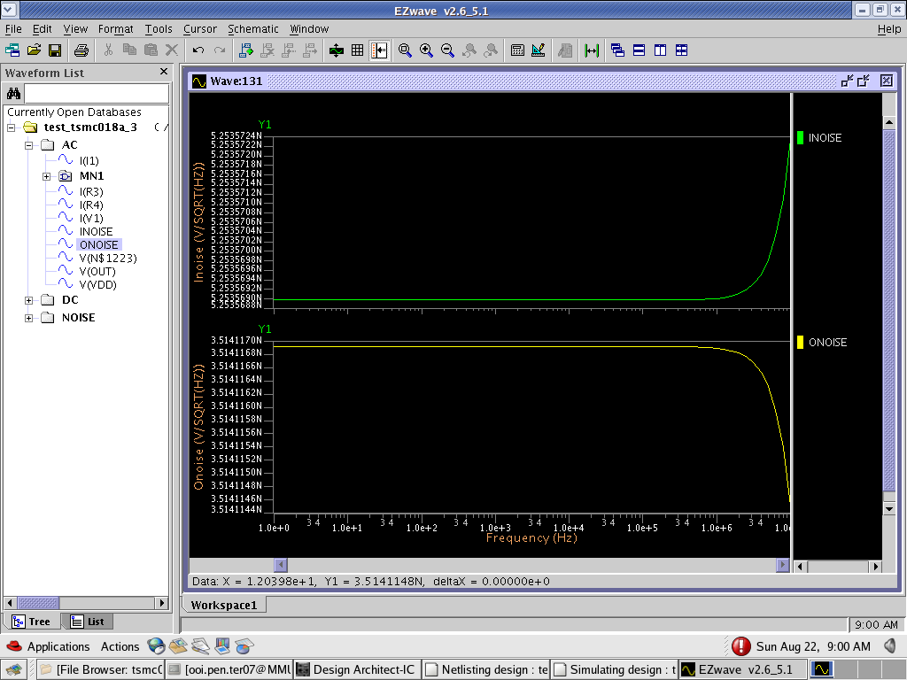
and what's the output should i get ?
pls help:cry:

Added after 6 minutes:

I don't understand .Why people help others in their posts, but nobody willing to help me ?

Did i post anything wrong ?
 

ricopt said:
...............
Did i post anything wrong ?

No, nothing is wrong. But very unspecific. It is not clear what your problem is.
Do you know the difference between an opamp and a CFA?
Do you know somethiung about feedback and WHY feedback is applied?
 

    ricopt

    Points: 2
    Helpful Answer Positive Rating
I sounds like you're asking forum members to retell a text book. If you have specific questions related
to your design, you should tell them, preferably including a circuit schematic.
 

    ricopt

    Points: 2
    Helpful Answer Positive Rating
But llast time, i did posted a design and wanted to get answer from anyone, but nobody wanted to response to me.and i need the answer urgently.


i will post up my design
It is a shunt feedback transimpedance amplifier with basic configuration
What should i put for my input and what should i get for my output to prove that my circuit is working ?


Added after 1 minutes:

FvM said:
I sounds like you're asking forum members to retell a text book. If you have specific questions related
to your design, you should tell them, preferably including a circuit schematic.


If i can find a book or ebook regarding my circuit, i no need come to this arrogant forum to ask this kind of stupid question asking for help from all arrogant ppl
 

I am not sure I would call that a transimpedance amplifier. To me a transimpedance amplifier converts a current to a voltage and has a low input resistance. Your circuit looks more like a voltage amplifier although it depends on transistor sizing and resistor values.

I would suggest a DC current sweep first - sweep the input current and observe the output voltage.

You look like you are already doing an AC sweep which is good - it will give you the transimpedance (voltage out versus current in). That should normally be close to the value of the feedback resistor but if the open loop gain is low then the transimpedance could also be low.

It is worthwhile looking at the voltage on the input when doing you AC current analysis. That will give you an idea of how low the input impedance is. Another option is to use a voltage source with series resistor as the input source. Then if you look at the voltage on the transistor gate you can find the effective input resistance.

Keith
 

    ricopt

    Points: 2
    Helpful Answer Positive Rating
I agree, that a single transistor with voltage controlled current feedback can be described as a transimpedance
amplifier. R1 and R2 should be omitted, they are not required for the basic operation.

But as Keith mentioned, it's far from an ideal transimpedance amplifier. So it depends on the purpose, if it's of
practical use.

P.S.: I see, that Razavi presents a common gate stage as transimpedance amplifier prototype.
 

    ricopt

    Points: 2
    Helpful Answer Positive Rating
Keith, FvM :

Thanks guys
For your info,the R1 and R2 is for voltage divide to bias the transistor in sat mode.

I am beginner to it.That's y i need help.i am testing on ideal circuit first.Cuz i duno what my output will be and am i doing the right simulation.I am studying Sackinger book.But is not enough.I have look thru tons of journals ,but they dun have the basic one and a output and guidance.That's y i need help here.
 

For my opinion - the shown circuit is far away from being a "transimpedance amplifier" - particularly since a MOSFET in common source configuration is used.
Where is the point (node) that transfers a current into a voltage?
The output voltage solely is determined by the gate voltage - even if the input signal might be a current that produces a voltage at the gate.
It might be interesting to learn why RICOPT calls this circuit "transimpedance amp" and the most important question is: What is the purpose of the circuit or what is RICOPT's goal?
 

    ricopt

    Points: 2
    Helpful Answer Positive Rating
The output voltage solely is determined by the gate voltage
You'll find the same behaviour - output voltage depends "solely" on the input voltage - with most transimpedance amplifiers that are driven by a voltage. But it's not reasonable to drive a transimpedance amplifier from a voltage source.

Clearly the limited gm of a single MOSFET produces only poor transconductance behaviour.

Regarding R1/R2, I think, the feedback resistor is sufficient for a suitable DC bias of the presented circuit.
 

    ricopt

    Points: 2
    Helpful Answer Positive Rating
LvW:

Thanks dude for the opinion.I will attach a file which that's where i get the circuit from.This circuit is just the basic type.and I need to simulate out the output just to prove that the circuit is working .That's all.I need to simulate out the transimpedance(Vout /Iin) Like what Keith said.

FvM:

Thanks.Did i insert the output at the correct place ?Or i need to change to get correct output ?I refer this from this journal that i've attached.Please let me know if i m wrong
 

can anyone help me take a look at my waveform ?

I am not sure which component should i put .

Keith ,
I have insert Vout/Iin, but the waveform just one straight line....correct ?


You should follow Keith suggestions first.

At least, check the bias point to see, if the transistor is operating in linear range.
Generally, the feedback resistor should be considerably higher than the load resistor, I think.
Also gm*RL > 1 is required.
 

    ricopt

    Points: 2
    Helpful Answer Positive Rating
but i thought i need to let it in saturation mode ?
 

Yes, saturation region is correct. (Just a misunderstanding of terms)
 

    ricopt

    Points: 2
    Helpful Answer Positive Rating
FvM:

bro, now my problem is i duno which parameter should i plot
i know i need to plot Vout/Iin, but if i take from AC, i get MAgnitude(dB) vs freq(HZ)
instead of Voltage vs ampere.and if i take from DC, i got just a straight line.
That's my problem.If i can solve that, then everything solved
 

A dB plot will simply be a dB representation of the transimpedance, so 20dB would mean 10 ohms, 40dB would mean 100 ohms etc.

A plot of Vout against Iin should be a straight line with a slope which is the transimpedance. It will deviate from a sensible slope at a certain current which is where it ceases to be a transimpedance amplifier.

Keith
 

    ricopt

    Points: 2
    Helpful Answer Positive Rating
bro,

this is my Vout....how i see the transimpedance ?

where you get that information from ?(20db=10ohm) ?


Added after 13 minutes:

This is my Vout/Iin


I use the Vout and I(I1) from the AC is it correct ?
 

For the Vout against Iin simulation you should use a DC analysis, not AC, otherwise you get the same answer as the AC analysis.

From the AC analysis you have around 30dB which is around 20 ohms - not a lot! Your feedback resistor is 1k so it is not behaving like a transimpedance amplifier.

Plotting and AC analysis often gives dB but in this case the conversion from ohms to dB can be confusing. The transimpedance will be displayed as 20log(Vout/Iin) so 20 ohms is around 30dB.

Keith
 

    ricopt

    Points: 2
    Helpful Answer Positive Rating
Status
Not open for further replies.

Part and Inventory Search

Welcome to EDABoard.com

Sponsor

Back
Top