Continue to Site

Welcome to EDAboard.com

Welcome to our site! EDAboard.com is an international Electronics Discussion Forum focused on EDA software, circuits, schematics, books, theory, papers, asic, pld, 8051, DSP, Network, RF, Analog Design, PCB, Service Manuals... and a whole lot more! To participate you need to register. Registration is free. Click here to register now.

Automatic Emergency Backup Power with Charger

Status
Not open for further replies.

aq_mishu

Full Member level 4
Joined
Jul 16, 2007
Messages
212
Helped
1
Reputation
2
Reaction score
1
Trophy points
1,298
Activity points
3,402
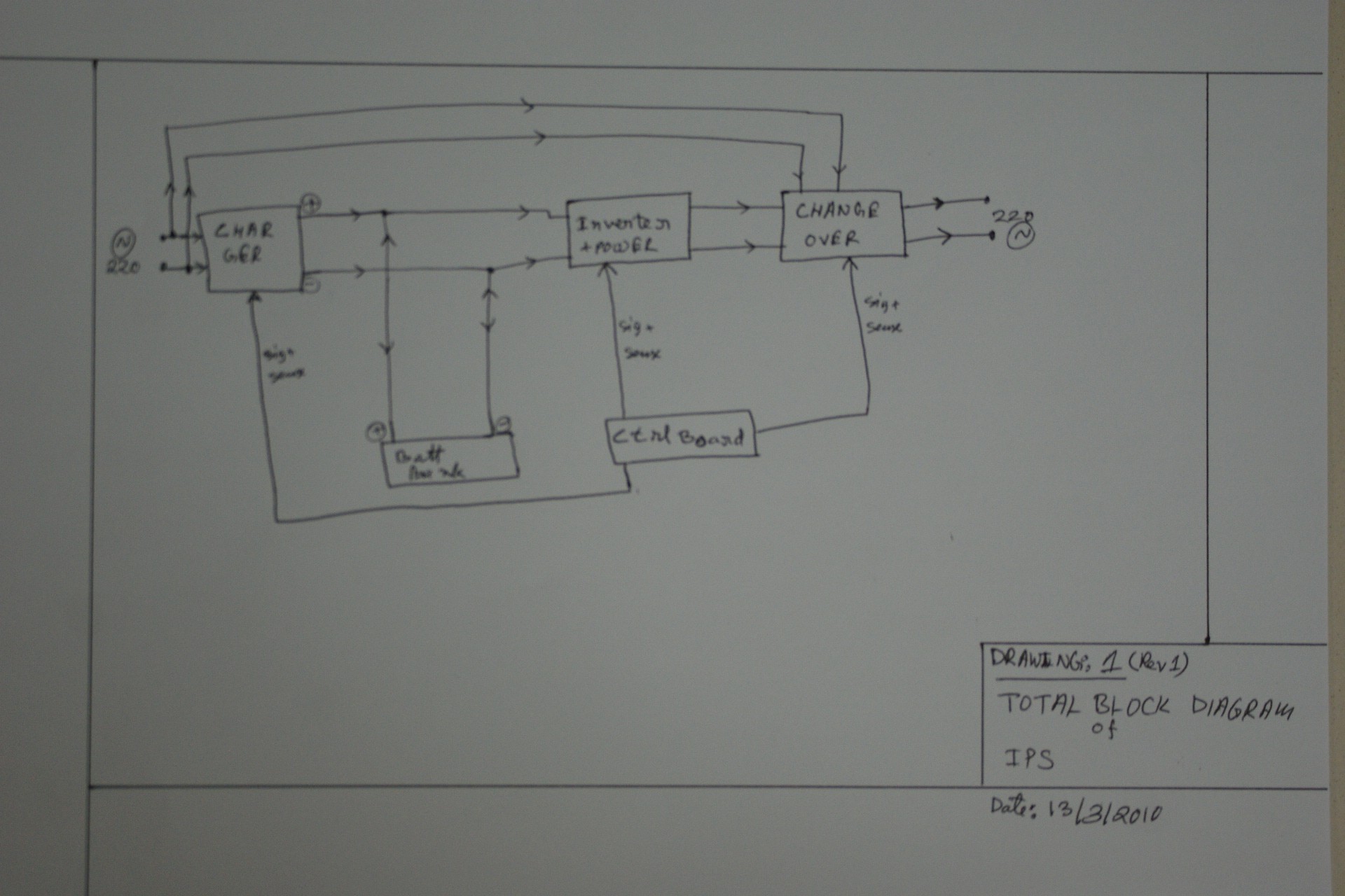
Guys, Please help me to design this... (Which may lead to finally design a Instant Power Supply (IPS) as backup power source for household with built in charger, inverter etc.)

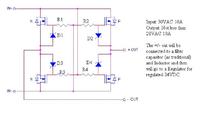
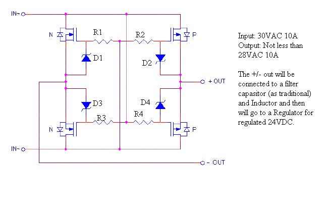
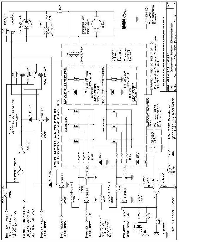
I first want to convert all my existing PSUs (Linear) to SMPS based. So voltage regulation will be by switching mode... with high current/controllable current... But as general bridge rectifier of diodes involve large voltage drop and high wattage consumtion, means low efficiency, i want to keep it within 80% or above. Thus my plan is to use MOSFet instead of diode. after a lot og googleing, i found it... now can you tell me the values?? Say I need 30VAC with 10A (Max... if more, i'll work on it later) and regulated output would be 24VDC. As like linear ones, can i use the same filter part to filter ripples? first attempt of mine is to replace the bridge with mosfet and then to change the regulator with a pwm. step by step... so finally it will be a complete big project...

now guys, i need holp on designing this bridge... here is the file i got...


Mishu~~
 

Re: MOSFet Bridge Rectifier problem...

just my opinion...
so the input is the usual sine wave....
those Mosfets will switch on SLOWLY, so existing capacitors should be ok.
But I don't think the efficiency you are looking for will be there because of that slowness....
 

Re: MOSFet Bridge Rectifier problem...

I need an around 20+ amp on 24V (27v and 29v actually for final) for a charger for my inverter (or IPS). Thus if linear with diode, I can use a high amp bridge but due to Vf of the diode and linearity (i call it) there will be huge wattage of waste. so the system will not be so efficient. Also, do i then need more fast???

Well, describing more, The input is some 30V AC sine (or 18VAC Sine for 12V system). The bridge must rectify the full wave and then capacitors and inductors will filter... it will simple replace the traditional diode bridge for low loss... advice please...
 

Re: MOSFet Bridge Rectifier problem...

dont worry bout the filtering crap... thats not the hard part of your question.
i know this topic is old, but mosfets will/are replace diodes, so its important.

basically... pretend the body diode of each fet is a diode in a full bridge... orient the fets that way... set the body diodes up to accomplish the task at hand, just forget about the mosfet part. ...this is true even if just using one fet as a diode
(nmos: gate on "+IN" rail, DRAIN gets "-in".. source is "our new ground".... try reversing input polarity... open circuit...(keep gate charge low(zener if needed)))

anyway... once the circuit "works" as a full bridge rectifier via the body diodes only (all fets off), if we are able to turn the fets on we save power loss...

when should we turn em on? when there is current flow.
so a comparator senses source-drain of each fet..(one with a very low threshold... few mV ideally)... that comparator signals a fet driver: fet on. power dissapation now 0.001*1000 instead of 0.7*1000 (for me anyway).. oobviously repeat for all fets.

initially i would slap some external diodes in || w/ the body diodes, ... schottky so that if its not working they burn out instead of fets


i have never seen this done, typically its only one fet on a secondary winding or two on two secondrys... i do however think it should be done "more"... im sure its done though.
 

Inverter and Charger

Guys, I have to biuld an Inverter with Charger. Modular of course and i know i can buy one, but i wish to make one... Please dont mension any advanced ICs like ADE7756 for power measurement or Something from ADE for synchro rectifier. my needs are here...

I need a rectifier... made of MOSFET instead of diode... and then a regulator... (SMPS is good but since here smps transformer is not that much available, well, can i use linear regulator like lm338 with pass MOSFET (Instead of bjt)? I need to charge a 48V battery bank and I want to use the same method with some current control of not greater than 20A. My previous post is at for referance on the charger. I just need to make it efficient. Once the charger is done, then I'll need the Inverter...

Well, the inverter is also modular, 19"rack mountable and so the control logic part is... so any upgrade is just replace the module... well, I found and I liked it. But is just an inverter... so i have to add voltage sense on AC, frequency measure of AC and current monitor of AC. MEans I need to continiously monitor the AC RMS voltage, current and then i'll take desicion. any help guys??

Mishu~
 

Re: MOSFet Bridge Rectifier problem...

guys, i really need help...
 

Re: MOSFet Bridge Rectifier problem...

Hi Mishu.

I like the inverter design, it's a good use of a microprocessor to provide the correct drive signals for the MOSFETs. I'm not sure about the comment on the schematic about damage to the PIC, I would have done things differently.

Unfortunately, this kind of inverter does not easily allow control of it's output so even if you monitored the output voltage and current, I'm not sure you could stabilize it.
If you want to try, you can measure the voltage by connecting one side of the transformer secondary (HV side) to the negative rail then sense the other side through a rectifier and suitable potential divider to drop the voltage to < 5V. The PIC has analog inputs which you can use to measure the voltage. The frequency is decided by the software so there is no need to monitor that. As for the output current, it isn't easy to measure but it is proportional to the transformer input current and that in turn is proportional to the MOSFET current. You could put a small value resistor, say 0.05Ω in the source connection and monitor the voltage dropped across it. If you use the methods I suggest, the voltage and current sensing are both relative to ground so you can read directly into the ADC.

Brian.
 

Re: MOSFet Bridge Rectifier problem...

Dear Brian Sir,
Thanks for reply... well, though the thing has been designed in PIC, i am planning to use using AVR. I am making it just for me... (no commercial matter... thus price doesn't matter that much than the real quality and reliability and stability.). My plan is to use an ATTiny/mega8 (depends on availibility in my country's local retail market) for frequency generation. Or u can say just for driving the mosfet. Dafinitely modified sine (sq wave indeed). And for protecting the AVR, i can use an opto-coupler. To prevent Mosfet, i can use zener there or also the capasitor (that used) from the spike of inductive load.

there will be a complete different AVR for for monitoring and control of other AVRs/devices like change over, etc. For voltage measure, I need to make a AC DVM in the control AVR. Also need to measure current. For so, I got an idea from a site (I forgot the URL, i have saved it as PDF). It is said that using 0.05Ohm 5W 15 in Parallel for 2KVA. So based on that, I can scale it up. This shunt needs to be forced air cooled. Another approach is using CT. But since AC, I need to figure out a way... also for each 10 readings, i want to consider the max value of reading instead of average... since it's about load sense and safety, i can consider a little over estimation. I have made some drawings (like previous, paper... and i'll post them after taking pic.). I'll post all of them (including the plans, block diagrams, schematic) for sharing and improvement. And hope, finally it will become a rack mountable modular 5KVA IPS finally...

Mishu~

Added after 17 minutes:

The block Diagram as I planned...


And the referance of protecting MOSFET using Zener as i tolad already is here...


Note that, there are thousands of schematic on the net. but in my country, so many things are not available including SMPS transformer, regulators, drivers, even MOSFETs of some range and energy metering IC (like ADE75xx).

Mishu~
 

Re: MOSFet Bridge Rectifier problem...

well, guys, I am planning it... made the block diagram and also making the changeover... basically it must be fail safe and response time should be as minimum as possible... thus i am planning to add a backup battery (instead of the storage battery) thing for zero down of the main control board... basically the main control board will get the power from the output of the changeover... so either way, it will get power to run. but since there will be several relays, (infact a bank of relay), i am thinking of using a UPS kind battery for just keeping the board up all the time between the power changeover... because if the relay cant make it on time (due to a bit shortage of mA), then the system will become unstable and will not go to backup power mode... so here is the plan...


Now tell me how should i sense the main voltage?? And i need to measure also the RMS voltage and i need fast response in the case if power failure.. and voltage sense must be for output (no matter if mains available or not) but in case of voltage failure, it must sense at a certain level of voltage say for 220VAC, it must consider a 150VAC as a failure and switch over to inverter... ideas guys???
Mishu~
 

Re: MOSFet Bridge Rectifier problem...

Guys, I am posting the block and change over block diagram... i am also working on making the things and will upload... meanwhile, i need your kind help on where i struck... so that we can finish it up...

Mishu~
 

Re: MOSFet Bridge Rectifier problem...

I have a similar system for switching to inverter power if the mains power fails. It son a solar water heating system that overheats if the pump isn't running so it's essential to keep power on it, at least during the daytime.

You can simplify the switching. Use one 2-pole change-over relay with a mains powered coil so it energizes whenever the normal power is present. Use one pole to change from mains to inverter (it's correct in your schematics) and the other pole to switch the DC power to the inverter. Wire the contacts so the DC is normally off when mains is present and the mains goes to the load. If the power fails, the relay de-energizes and switched DC on to the inverter and the inverted output to the load.

It's only one component to do the job!

Brian
 

MOSFet Bridge Rectifier problem...

Hallo,
I did read yet over ST`s STPS50U100C -"Ultralow forward voltage power Schottky rectifier",0.64Vtyp (0.7Vmax) 2x25A, 100V in a TO220AB & I2Pak Packages :)
K
 

Re: MOSFet Bridge Rectifier problem...

the major problem here in my country is so many components are not available yet... anyway... im reading through and giving u guys feedback...

Added after 3 minutes:

betwixt said:
You can simplify the switching. Use one 2-pole change-over relay with a mains powered coil so it energizes whenever the normal power is present. Use one pole to change from mains to inverter (it's correct in your schematics) and the other pole to switch the DC power to the inverter. Wire the contacts so the DC is normally off when mains is present and the mains goes to the load. If the power fails, the relay de-energizes and switched DC on to the inverter and the inverted output to the load.

Well, actually i am doing the opposite thing... just the opposite... now can u tell me the merits and demerits of both way??? and ofcourse, i need DC for several sensing/etc part... but it should be fast response... like after AC-DC, for the capasitor's slow discharge rate, it clamps the whole thing for a while... this creates a delay... which i want to eliminate..

well, first, it i make the change over just the opposite of you said, energize by the DC and NC at mains, what can bring the differance?
Mishu~
 

Re: MOSFet Bridge Rectifier problem...

guys, need help again... can you tell me how exactly i can make a 20A 48VDC PSU?? I mean to charge the battery, I need stable voltage and 20A max current (ofcourse 20A current and i'll never let the battery to consume more than that...) I need to use MOSFET there... instead of BJT. I have found some 12V 30A DC PSU design where they used BJTs like 2955. But i am planning for MOSFET instead of those BJT. so guys, any ideas???
 

Re: MOSFet Bridge Rectifier problem...

The normal method of rectification is just to use Shottky diodes and accept the voltage drop. It will be lower than normal silicon types and better suited to fast switching times.

Here is an idea for you - I have never tried it so please don't ask for a schematic, it is JUST an idea at the moment:

Use Mosfets as the bridge rectifiers so you have a low forward resistance but drive them from opto-couplers and a microprocessor. In other words, turn the Mosfets into switches which only conduct on the half cycles a normal diode would, but turn them fully on during the conduction cycle so the resistance is low through the whole conduction period. You would have to sense the phase of the AC and compensate for the phase shift in the transformer but that should be a constant timing offset.

So effectively, instead of a 0.5V drop in the diode you have a few milli-Ohms resistance instead.

I can see a whole heap of problems with getting Vgs right in an AC environment but it might be worth an experiment.

Brian.
 

Re: MOSFet Bridge Rectifier problem...

Refering to simple self-steering MOSFET bridge at the top of this thread, I'd like to mention, that it's performing not bad.

The main disadvantage is the usage of P-FETs, that have higher rdson than N-FET with same transistor area. A self-steering N-FET
only circuit would need some additional circuitry, e.g. for the gate driver supply, but should be possible as well.
 

Re: MOSFet Bridge Rectifier problem...

phase matching is tough at my stage of knowledge... anyway... i'm planning to use an n channel mosfet and make it... if i fail, i may go for other method (diode) said by betwixt. Also well, no matter how I make this rectifier, i need a regulated voltage (i am planning for 317/338) and using pass transistor... but actually I wish to replace the BJT with mosfets... can i do so??? (constant bias ofcourse since it will supply additional current... just replacement of bjt)???

Mishu~
 

Re: MOSFet Bridge Rectifier problem...


Guys, I just got it from a site. (I forgot the link). Now i need help on improving it... first of all, my target is 48V. 30A. so i am planning to use lm338. And it's better to use mosfet... instead of bjt. but i can use bjt infact... but i need 30a cont load with 48V... (I mean for charging 48V battery bank).

Some ppl says about using a separate transformer... but do i need it? or just one transformer is okey?? My transformer's allowable voltage is 180-250. I mean the charger will keep 48V charging (around 67V@180) so in low voltage or some high voltage, i can cont my charging... Please guys, help me...

Mishu~
 

Status
Not open for further replies.

Similar threads

Part and Inventory Search

Welcome to EDABoard.com

Sponsor

Back
Top