Faizan Jawaid
Full Member level 3
- Joined
- Jul 17, 2008
- Messages
- 189
- Helped
- 23
- Reputation
- 46
- Reaction score
- 5
- Trophy points
- 1,298
- Location
- Karachi, Pakistan
- Activity points
- 2,336
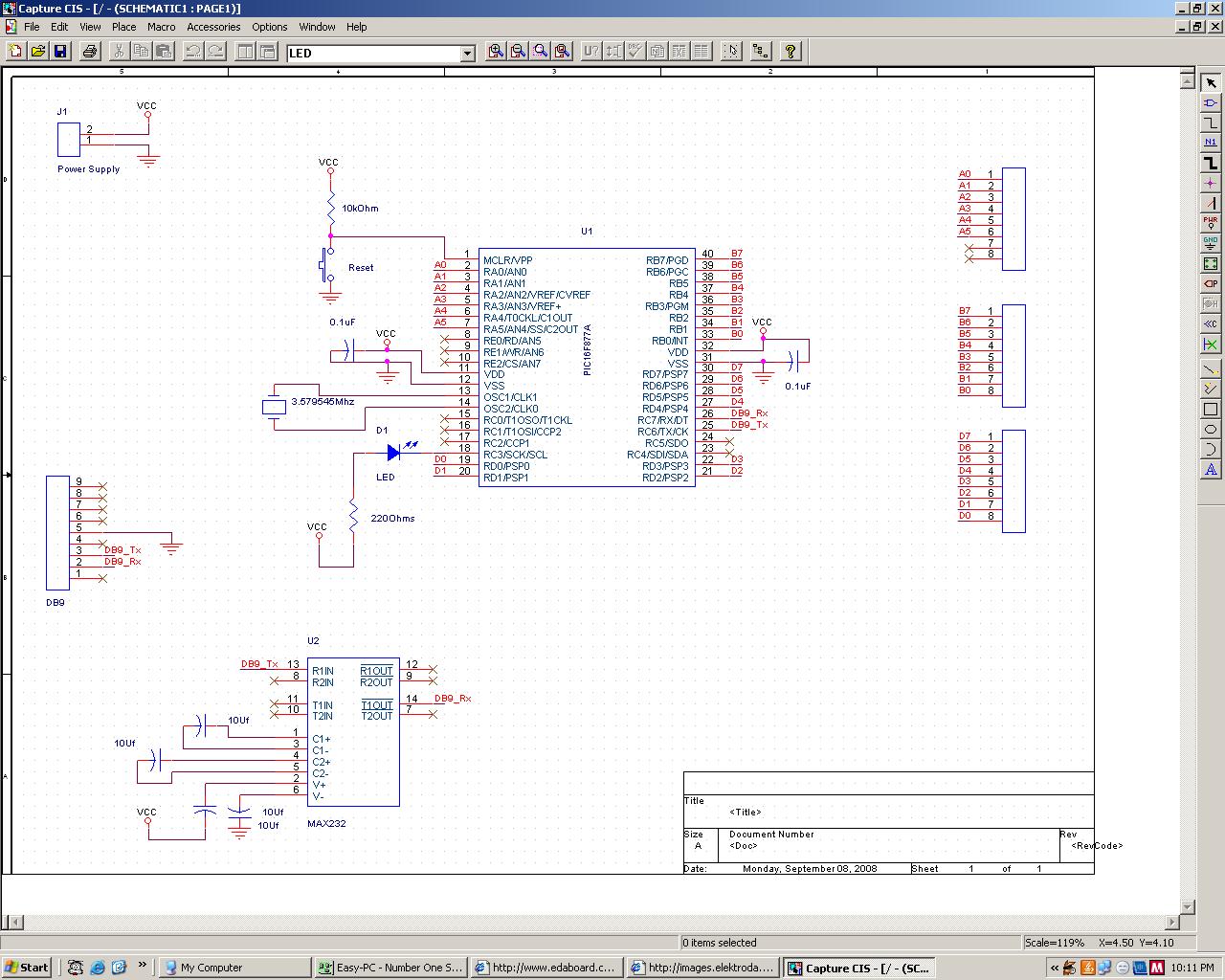
This is not big issue buddy. Please post a complete schematic.
Follow along with the video below to see how to install our site as a web app on your home screen.
Note: This feature may not be available in some browsers.
#include<16f877A.h>
//#use delay (clock=20000000)
#use delay (clock=03579545)
#fuses NODEBUG,HS,NOWDT,PUT,NOPROTECT

#use rs232(baud=2400,xmit=PIN_C6,rcv=PIN_C7)
main()
{
   int i;

   set_tris_a(0x00); //se
   set_tris_b(0x00); //se

   set_tris_d(0x00); //se
   set_tris_e(0x00); //se


   while(1) {
            i=65;
            do
               {
               putc(i);
               delay_ms(1000);
               i++;
               }
             while(i<=122);
            }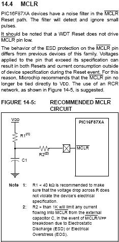
}") ) Caps near xtall MUST BE. Some examples of MCU can start without it, but it will not be good work. About serial resistor with MCLR pin: without this resistor your device mau be broken at reset time, because of triac effect. Read Microchip manuals. And what about fuse bits? (BOREN & WDT)
) Caps near xtall MUST BE. Some examples of MCU can start without it, but it will not be good work. About serial resistor with MCLR pin: without this resistor your device mau be broken at reset time, because of triac effect. Read Microchip manuals. And what about fuse bits? (BOREN & WDT)b4bb4ge said:I am having the same problems with the UART and my body coming close / touching the microprocessor and then the system freeks out.
I am using both the pic16F88 and a Pic18F and they are both having this issue.
When / if I solve this problem I will let you know what solved it for me.
#use delay (clock=20000000)#use delay (clock=20050000)