Continue to Site

Welcome to EDAboard.com

Welcome to our site! EDAboard.com is an international Electronics Discussion Forum focused on EDA software, circuits, schematics, books, theory, papers, asic, pld, 8051, DSP, Network, RF, Analog Design, PCB, Service Manuals... and a whole lot more! To participate you need to register. Registration is free. Click here to register now.

Controlling 2 stepper motors with PIC16F84A and 74LS244

Status
Not open for further replies.

engrjsilvestre

Newbie level 4
Joined
Aug 28, 2008
Messages
6
Helped
0
Reputation
0
Reaction score
0
Trophy points
1,281
Activity points
1,344
pic16f84 die

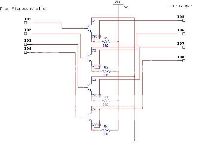
Im currently working on a school project involving the control of 2 stepper motors using a PIC microcontroller.


At the moment Im trying to learn programming PIC's, since we were taught with an MTS 88.C trainer, my transition has been quite tough. However I encountered this I/O board circuit at our lab involving a 74LS244 IC to control a fairly large Stepper motor.

Screenshot777.jpg


The 5V stepper motor I plan to control is this:

Screenshot778.jpg


However I am greatly unsure if the circuit is a suitable driver for the stepper motor, or if the circuit can be "compatible" to the PIC.

many thanks if you could help me out in clarifying this. :D
 

pic16f84 stepper motor controller

i dont understand why TIP31 transistors are used...u have`nt connect the coil terminal to the collector of TIP31...and 100 resistor will limit current...if the step motor rated voltage is same as the Vcc (5v) of transistor resistor is of no use....

Try this circuit. it can handle upto 800mA...According to the post schematic motor looks not greater than 800mA... and 74LS244 is compatible with PIC MCU...simple TTL logic buffers...
 
pic16f84 stepper motor

Faizan Jawaid said:
i dont understand why TIP31 transistors are used...u have`nt connect the coil terminal to the collector of TIP31...and 100 resistor will limit current...if the step motor rated voltage is same as the Vcc (5v) of transistor resistor is of no use....

Try this circuit. it can handle upto 800mA...According to the post schematic motor looks not greater than 800mA... and 74LS244 is compatible with PIC MCU...simple TTL logic buffers...

Thanks a lot, the first schematic is from the I/O board for the MTS 88.C I thought of using it since this is my first time building with a stepper motor, and that circuit is the first one Ive encountered which I was able to operate a stepper with.

I didnt realize that it has those problems that you have stated, thanks again :D
 

two stepper motors

Hi,
Check carefully again, are n't the collectors of each pair of transistors in your original circuit shorted? In that case, your circuit should be OK.

Regards,
Laktronics
 

pic16f84 + motor bipolar

hi,
your motor seems to be having a current rating near 500mA. If that's true i would suggest you use ULN-2003 as this will reduce the need of transistors in your circuit and also cuts down the cost of your project. The transistors used in your circuit is merely used as a darlington pair which provides the the isolation as well as the necessary current to the circuit. ULN takes care of that.

Moreover you need to look for the back emf that the motor coil generates,,,due to which motor does not run smoothly.

For programming PIC you can use other compilers also(which allows codes to b written in C),,,,or still you can use a different microcontroller
 

pic bas stepper

laktronics said:
Hi,
Check carefully again, are n't the collectors of each pair of transistors in your original circuit shorted? In that case, your circuit should be OK.

Regards,
Laktronics

They are not shorted, but motor coils ends should be connected to collectors of TIP transistors and everything will be as it should be. Resistor 100E is oull down for TIP's base, not current limit.

I would use Zetex ZTX696B (or simillar) instead of 2n2222. Small and high current rating available.
 

darlington pnp pic16f

james bond007 said:
hi,
your motor seems to be having a current rating near 500mA. If that's true i would suggest you use ULN-2003 as this will reduce the need of transistors in your circuit and also cuts down the cost of your project. The transistors used in your circuit is merely used as a darlington pair which provides the the isolation as well as the necessary current to the circuit. ULN takes care of that.

If I were to use a ULN2003 IC, then how would I connect 4 wire steppers? the example from
this site
shows how to connect 6 wire steppers to the ULN2003, I think the second circuit in that site matches my needs does that mean Ill have to ignore the wire 2 and 5 connections on the stepper?
 

stepper driver with pic16f84a

I am sorry, but I did not pay attention to motor you are going to use, as nobody here did.
Motor you have has only 4 wires, which means you can run it only in bipolar mode. That means that driver for each wire has to be bipolar, or in other terms it has to both source and sink current depending on state required.
ULN or discrete circuits that were posted here by you and others will not work.

How should driver look like depends on your motor data. Do you have any idea of required driving voltage/current for your motors?

Actually 4th (last on the bottom) circuit on the page you just posted would work for you, one with L293 driver.

Hope this helps.
 

stepper motor driver using l293d and pic16f84a

Sinisa said:
I am sorry, but I did not pay attention to motor you are going to use, as nobody here did.
Motor you have has only 4 wires, which means you can run it only in bipolar mode. That means that driver for each wire has to be bipolar, or in other terms it has to both source and sink current depending on state required.
ULN or discrete circuits that were posted here by you and others will not work.

How should driver look like depends on your motor data. Do you have any idea of required driving voltage/current for your motors?

Actually 4th (last on the bottom) circuit on the page you just posted would work for you, one with L293 driver.

Hope this helps.


the motor Im using requires 5V and approx. 500mA

For it to rotate, one of the four wires will have to be connected to source and the rest is at ground. sort of like
1000
0100
0010
0001

Ive already assembled the circuit for the MCU but I was told that
I might be needing two power sources instead,
one for MCU and another for the steppers.
 

pic16f84 snd project

Some suggestions should be treated with caution, e. g. using a 2N2222 for 500 or even 800 mA load current.
DC current gain below 100 (maybe below 50). Driving the transistor through 2k2 with 500 mA load would make
it melt down quickly.

Using a freewheeling diode to the same supply voltage for unipolar driven stepper is generally a bad idea, cause
it slows down the current decay and limits the achievable motor speed.

As said, the present 4-wire motor is obviously designed for bipolar drive and needs bridge drivers. It's probably
more easy to get another motor then designing a bridge driver.

Regarding need for separated supply, if the motor can be operated with 5 V, it could use a common supply,
if it has sufficient bypass capacitors and ground wiring, and the voltage regulation is stable also with
switched load current.
 

how to use bypass capacitors with stepper motors

I think your problem can be solved if you build a L297-L298 stepper motor driver. It will be a good project.
Basically L298 is a driver IC that can supply a max. current upto 4A(however it should not be used for over 2A). It is specifically made to drive bipolar motors like yous. It has got a current limiting. If you can work on near 1.3A you can use L293 in place of L298, but it doesn't have current limiting. Howver i would recommend you to use L298 as it provides you with more flexibility.

secondly, I suggest you use L297. It is a stepper motor controller and it generates the pulses required to drive a motor. In this way your project will be moe flexible and you can use the same circuit to drive different motors(by some modification even unipolar motors). And your project will also look better.
I have completed this project some year back so if you need any specific help feel free to ask me.

Added after 3 minutes:

for details on this circuit click on the folowing link


Added after 2 minutes:

even ULN can be used (i guess) for controlling bipolar motors with some change in programming codes. But generally bipolar motors have current rating more than 500mA which ULN cant provide

Added after 2 minutes:

for using two power supplies I think its always good to dedicate a seperate power supply to a motor,,,however this ain't necessary.
 

stepper pic16f

FvM said:
Some suggestions should be treated with caution, e. g. using a 2N2222 for 500 or even 800 mA load current.
DC current gain below 100 (maybe below 50). Driving the transistor through 2k2 with 500 mA load would make
it melt down quickly.

Using a freewheeling diode to the same supply voltage for unipolar driven stepper is generally a bad idea, cause
it slows down the current decay and limits the achievable motor speed.
. Could you please tell why the transistor will melt? 2N2222 has continous collector current of 800mA.

Secondly freewheeling diode to same voltage for uni-polar...how it slows down current decay?
 

pic16f84 with l298

Could you please tell why the transistor will melt? 2N2222 has continous collector current of 800mA.

FVM's post contains answer to your question. Simply, transistor might not open fully because of insufficient base current and therefore would heat too much.

Secondly freewheeling diode to same voltage for uni-polar...how it slows down current decay?

Because diode would do its job, energy would slowly dissipate in coils resistance (mostly). If zener diode is used in series with diode, or in some other way collector voltage was allowed to reach closer to transistors maximum rating, current would die off more quickly and therefore allow for faster motor running.

Again these techniques are a bit more advanced for beginer and engrjsilvestre would be happy with just basic circuit that works with his motor. He can learn how to improve perfomance once he has basic circuit running.

even ULN can be used (i guess) for controlling bipolar motors with some change in programming codes. But generally bipolar motors have current rating more than 500mA which ULN cant provide
How?
 
stepper motor 6 wire vcc

There was a circuit prescribed to me by a friend here, using only 9013 (NPN BJT) Transistors

driver-1.jpg


However I noticed a drop in voltage of about 1~1.5V on the connectors, the driver suggested to me could easily light up LEDs but the drop proved too much of a loss to drive the steppers. Is it possible that I can compensate for the loss by increasing the source? I worry that the PIC might get killed, but Im in a pinch now.

Ive considered the L293D ICs however, these cost more than the PIC16F84A IC and given that Ill be using 2 steppers Ill be going over my budget. I could easily wire the entire circuit tomorrow if the above issue on increasing the source could be answered because I should be showing the prototype by Wednesday.
 

74ls244 stepper motor parallel

Thanks to Sinisa for elaborating some details.

engrjsilvestre, your recent circuits has obvious errors, e.g. reversed transistors, and can't work as shown. The basic idea,
to use load resistors instead of push-pull (bridge) drivers however can work. I had it in mind already, but found that using
another motor is a better suggestion. The main drawback is the power dissipation in resistors. It would even require a doubled
supply voltage (causing even more losses) to achieve similar torque than a bridge driver.

The circuit could be corrected by using PNP transistors.
 

schematic of stepper motor driven by pic16f84a

Thanks Sinisa. Could you please let me know from where do i get thorough knowledge on your concept of fast current decay (Its new for me). Any book or any reference?

Thanks alot.
 

simple pic16f84a based bipolar stepper control

use H-Bridge driver IC L293D very simple to use
 

stepper motor control pic16f84

Thanks Sinisa. Could you please let me know from where do i get thorough knowledge on your concept of fast current decay (Its new for me). Any book or any reference?

Sorry, I was away for few days. Well I don't know specific book I could recommend, but if you understand how inductors behave in switching circuits than it is fairly easy to think of how to interupt current in inductor more quickly. Books on switching power supply would have sections that would discuss effects of switching inductive load.


Basic formula of voltage accross switching transistor would be

V=L*dI/dt.

So if you want to interrupt current in as short time as possible, you have to select switching element that would withstand higher voltage when switching off and limit that voltage to safe level of your switching device. This can be acomplished in various ways, like anti parallel zener to switching device, zener in series with freewheeling diode (does this "freewheeling" name tells you something?), or some more advanced methods where rate of current change is controlled by voltage accross device (e.g.zener from collector to base of BJT), and some even better circuits where capacitors and inductors are used to recycle energy from inductor by returning it back to bus voltage.

Here is example of one of my projects where several amps had to be interrupted in two large coils as quickly as possible. Energy here is not recycled but rather dissipated at R1. C1 value is selected so at the peak voltage it does not exceed maximum rating of Vce0 for Q1. If R1 was replaced by inductor and with few more modifications, circuit could recycle energy form the coil.


I hope this helps you.
 

reduce dc motor speed using pic16f84a

Thanks alot Sinisa. I know now a little more about current decays. Specially your schematic clicked an idea that i can simulate small circuit for switching inductive loads for the analysis.
 

pic16f84a+motor

**broken link removed**

Look in the stepper section of Fred's pages.
<als>
 

Status
Not open for further replies.

Part and Inventory Search

Welcome to EDABoard.com

Sponsor

Back
Top