Continue to Site

Welcome to EDAboard.com

Welcome to our site! EDAboard.com is an international Electronics Discussion Forum focused on EDA software, circuits, schematics, books, theory, papers, asic, pld, 8051, DSP, Network, RF, Analog Design, PCB, Service Manuals... and a whole lot more! To participate you need to register. Registration is free. Click here to register now.

Colpitts oscillator in ADS

Status
Not open for further replies.

mirkata0

Newbie level 4
Joined
Sep 1, 2021
Messages
7
Helped
0
Reputation
0
Reaction score
0
Trophy points
1
Activity points
88
Hello everyone,
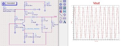
I am really struggling with designing a Colpitts oscillator for 2.4 Ghz. I know the principles and read a lot about it but my simulation in ADS does not work. I am spending hours on this without any progress and can't find where is my mistake. Would really appreciate if someone can give me advice on what I should do? Here is the circuit which I have designed. (and yeah i know that my bypass capacitor is not connected).
1636327832357.png
 

This variant of Colpitts Oscillator is not very appropriate for 2.45GHz.You should consider Modified Clapp Oscillator for this band.
 

I see the circuit oscillating at about 700 MHz in LTspice. A kick-start pulse is required as in any oscillator simulation, I presume it's also the case in ADS.

I agree with BigBoss, that colpitts is probably not the best oscillator topology for 2.4 GHz, in addition the LC values are inappropriate, 0.1 pF is lower than parasitic circuit capacitances, respectively you get much lower resonance. I assume an useful inductance value of a few nH.

1636361085560.png
 

Attachments

  • bfr540.zip
    1.7 KB · Views: 162

    mirkata0

    Points: 2
    Helpful Answer Positive Rating
There are few design mistakes on your schematic.
Use the schematic attached and it will work.
Try using a real RF transistor from ADS library.
 

Attachments

  • LO.jpg
    LO.jpg
    335.2 KB · Views: 349

    mirkata0

    Points: 2
    Helpful Answer Positive Rating
Since you're using ADS, why don't you use Oscillator Design Guide ?
Let me give you a sample design here to start-up.
Also, I recommend you to read Ulrich Rohde's textbooks and papers about oscillators at
He is the best known/living Oscillator/Signal Generation Guru. Follow him..

1636385968931.png

1636385985820.png

 
  • Like
Reactions: FvM

    mirkata0

    Points: 2
    Helpful Answer Positive Rating
Hello,
Thank you all for the help and suggestions. I want to use a real RF transistor BFR540. Is anyone familiar with downloading libraries from NXP for their models as I am only finding High Power Design Kits and not the one for my application? I cannot find the BFR540.
Thanks.
 

Hello,
Thank you all for the help and suggestions. I want to use a real RF transistor BFR540. Is anyone familiar with downloading libraries from NXP for their models as I am only finding High Power Design Kits and not the one for my application? I cannot find the BFR540.
Thanks.
BFR540 is an obsolete BJT, not recommended for new design.
I have designed an 2.4GHz VCO yesterday using with BFP193W ( Infineon) that is still available.
For your reference..
1636647998152.png

1636648130803.png

--- Updated ---

High Resolution Output
 

Attachments

  • 2.4GHz Clapp_output.pdf
    85.6 KB · Views: 180
  • 2.4GHz Clapp.pdf
    17.8 KB · Views: 193
Last edited:

1- try using a short stub transmission line for your tank circuit inductor, in oscillator designs using lumped inductors create problems in pcb.
2-since tank circuitry is a ratio of inductor/capacitor; first see how much inductor value you can get for a short stub inductor, then choose the capacitor value accordingly. you can use FR4 as your substrate.
3- try making your design more realistic by using transmission lines after first couple simulations. In oscillator design, stray capacitance from transmission lines are very critical in determining your Q.
 

    mirkata0

    Points: 2
    Helpful Answer Positive Rating
Hello. I followed your suggestions and designed this circuit:
1637493707076.png

However, I am not getting any oscillation from Vout.
1637493772517.png

Do you have any suggestions what could be wrong with the circuit?
Thank you all!
 

Not sure if the RF path fulfills the oscillation condition, but the bias point is surely inappropriate. Vbe of 450 mV doesn't even cause minimal collector current with a Si transistor.
 

Not sure if the RF path fulfills the oscillation condition, but the bias point is surely inappropriate. Vbe of 450 mV doesn't even cause minimal collector current with a Si transistor.
I got an oscillation but its not at the correct resonant frequency. I know that there are mismatches due to the distortion from microstrip lines but do you have any sugggestion how to increase the frequency. I am getting 1.6 Ghz while aiming for 2.4 GHz.
Thanks!
 

Make the value of C21 between 2pF and 3pF..
If is not oscillating, increase the value of R2.
 

Another example and verification of the previous circuit. Inspire from my designs.
Transmission Lines don't create distortion. You have to work much on Microwave Design Principles buddy..
 

Attachments

  • 2.4GHz Oscillator.pdf
    262.8 KB · Views: 220
  • 2.4GHz Oscillator HB Output Voltage.pdf
    168.7 KB · Views: 190
  • 2.4GHz Oscillator Output Spectrum.pdf
    166.8 KB · Views: 185
Last edited:

Make the value of C21 between 2pF and 3pF..
If is not oscillating, increase the value of R2.
Thanks!
I did that and managed to increase the frequnency up to 1.9GHz but no more. Do you have any other suggestions for changing components values to increase frequency?
 

Using a BFU630 transistor, and assuming there is not much parasitic inductrance of the seires microstrip transmission lines between L1 and base of M1, making C2 about 2pF you have to get around 2.4GHz oscillation.
If the parasitic inductance of the lines is high, you may have to decrease L1 value down to 0nH (short circuit).
 

Status
Not open for further replies.

Part and Inventory Search

Welcome to EDABoard.com

Sponsor

Back
Top