bzblues
Full Member level 1
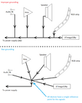
Would you be so kind to describe the "star point manner" please? I'm looking online but there are many examples for other kind of equipments and applications and its confusing to me. Logic tells me that I should add one extra cable to every ground connection that there is in the circuit, and join them all together in one mesh and connect them to the ground terminal on the PCB? and also the wire that runs from the ground terminal of the PCB to the metal plate?Hi,
To reduce noise:
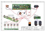
There are at least 5 GND connections on/to the PCB. Please use only one PCB GND connection and connect here all periferal GNDs with extra wires..in star point manner.
Additionally connect the cases of the pots to the star GND.
Klaus
![20201027_002212[1].jpg](/data/attachments/95/95210-e9a7acb351ce9804efaef0c16262c98d.jpg)
![20201027_002223[1].jpg](/data/attachments/95/95211-c9b9c6becde670c63efbd090a3baafe4.jpg)
![20201027_002253[1].jpg](/data/attachments/95/95212-95cee37e9d33c27a922eff1a426393e3.jpg)
") .
.