Continue to Site

Welcome to EDAboard.com

Welcome to our site! EDAboard.com is an international Electronics Discussion Forum focused on EDA software, circuits, schematics, books, theory, papers, asic, pld, 8051, DSP, Network, RF, Analog Design, PCB, Service Manuals... and a whole lot more! To participate you need to register. Registration is free. Click here to register now.

Question about Crystal oscillator

Status
Not open for further replies.

Em_13

Junior Member level 3
Joined
Feb 7, 2016
Messages
28
Helped
0
Reputation
0
Reaction score
0
Trophy points
1
Activity points
232
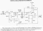
Hi,I am a beginner in RF circuits , have a question about this circuit:What does the Freq-set variable Inductor exactly do?I built this circuit and output frequency is fix despite changing this Inductor. only audio volume in receiver is changing.
Does "oscillator frequency" mean output frequency or it is about FM deviation for voice?Thanks.
OSCR941.jpg
 

Oscillator frequency means the output frequency of the carrier but I cannot see how it is going to work. It is adding a small load on the crystal. BB105 is acting like a capacitor (varactor) and the bias is set by the 10K potentiometer which is reasonable. 48MHz used in third overtone will be 144MHz which is beyond the normal FM range. You can use the 2nd overtone mode of the crystal by changing the capacitor triplet connecting the base to the ground.
 
  • Like
Reactions: Em_13

    Em_13

    Points: 2
    Helpful Answer Positive Rating
Thank you c_mitra.I want to use 33 Mhz crystal in 3rd overtone mode,Please help me to calculate the capacitor triplet for 99 mhz output.Is there any equation to calculate these capacitors?
 

You should be able to analyze the circuit yourself. This is not a very complicated one. Look at the picture carefully and you will be able to make out features.

The 270R and 0.01uF are used for the emitter biasing. They can be left as it is. They are not part of the oscillator tank circuit. The emitter needs to be lifted up from the ground to get proper base bias.

The 100pF and 150pF capacitors are in series. The 0.15uH inductor in parallel forms the tank circuit. Two caps are used to that we can get a tap on the tank voltage.

The effective capacitance of 100 and 150 pF in series will be around 60 pF. This and 0.15uH will give a frequency around 40MHz. The tank is also not working at the fundamental.

You will need to increase the inductor to 0.5uH to get this to oscillate around 25-30MHz.
 
  • Like
Reactions: Em_13

    Em_13

    Points: 2
    Helpful Answer Positive Rating
Status
Not open for further replies.

Part and Inventory Search

Welcome to EDABoard.com

Sponsor

Back
Top