Continue to Site

Welcome to EDAboard.com

Welcome to our site! EDAboard.com is an international Electronics Discussion Forum focused on EDA software, circuits, schematics, books, theory, papers, asic, pld, 8051, DSP, Network, RF, Analog Design, PCB, Service Manuals... and a whole lot more! To participate you need to register. Registration is free. Click here to register now.

problem inverter dc-dc 12vdc to 320vdc

Status
Not open for further replies.

marcosantonio

Newbie level 5
Joined
Feb 23, 2014
Messages
9
Helped
0
Reputation
0
Reaction score
0
Trophy points
1
Activity points
60
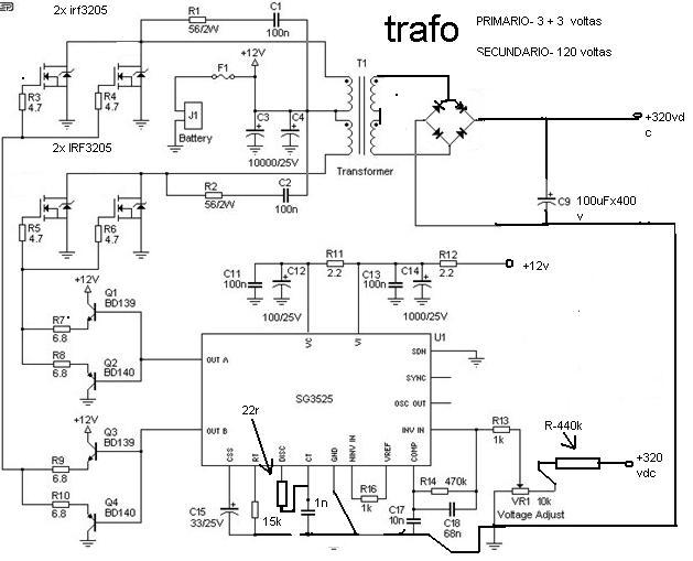
hello everyone I'm new to the forum and have come to ask for help I'm having trouble with a drive that I'm riding, I mounted the inverter with the input characteristics 12vdc to 320vdc 46klz frequency of the transformer is ee42, calculated the transformer for 350w output, up al fine the circuit works fine but when I put load 250w heats the fets but very much the same, I'm using 2 fets each side of the transformer and the IRF1404 fets arrives to catch fire heats up so much that I thought that was the proplem transformer and the transformer rebooked but not solved the problem, what is he happening. apologize for my English.
 

what driver circuit you are using?make sure mosfets are tightly intouch with heatsink.
 

Post the circuit schematic here so that we can evaluate some possible reason for that.


+++
 

hello in case of driver to using the BD139 and BD140 for fets, I envir an image inverter.


5871059600_1393181769.jpg
 

Please post your schematic as a very clear PNG or PDF file type instead of the fuzzy Jpeg file you posted that we cannot read.
Your Mosfets do not have a power supply voltage.
What is the part number for the driver IC?
 

I copied the link of figure above and pasted into address bar of Internet browser and worked nicely.


+++
 

The address of the image has something to do with this forum's website (obrezki.elektroda.pl) so why can't it automatically make the image large enough to see?
But it is still a FUZZY Jpeg file type.

1) The pins and labels on the 7805 regulator are backwards. The BD139 and BD140 are shown to have a 5V supply.
2) The IRF1010 Mosfets need a gate-source voltage at least 10V to fully turn on (and remain cool) but are getting only 4.3V which makes them very hot.
3) The Mosfets do not have a supply voltage fed to the center tap of the transformer.
4) Mosfet Q2 is shown connected backwards.
 

What values are C33, C34.

I do not see 12vdc connected to the transformer.

Your voltage regulator is 78L05. It looks like it is in backwards, and 5vdc is not enough voltage to drive the FET'S.
 

I posted this circuit is a reference of what I'm riding, but turned the fet this wrong but here in ciecuito rode this circuit correct photo is for an inverter input 24vdc to 350VDC and am adapting it to 12vdc to 320vdc my inverter 12vdc to 320vdc works fine but when I put it warms load is too much even what you think is it the transformer or fets.

- - - Updated - - -

the circuit of the photo is for input and output 24vdc 350VDC what I'm riding is 12vdc to 320vdc, the photo he uses a TL431 circuit and photocoupler in my'm not using these two pieces, and fets warming continues.
 

Maybe you cannot read or cannot remember things.
I said this in post #8: 2) The IRF1010 Mosfets need a gate-source voltage at least 10V to fully turn on (and remain cool) but are getting only 4.3V which makes them very hot.
 

hello!

You are right the fets have to work with 10v to stay fully open, but is working with 4.3V is what is doing the heating, what do you think I should do to resolve this defect?
 

Your Fets are only partially turned on so they are a resistor with volts across it and a high current in it which makes heat.

"Logic Level" Fets turn on perfectly with a gate-source voltage of 4.5V but they might not be available with a high voltage rating.
 

then the defect must be the fets? for me to solve the heating problem got to change the fets?
 

What we have here, is a failure to communicate. The design is the defect. Change the 78L05 to a 78L12 and your circuit will work.
 

    ahmetee

    Points: 2
    Helpful Answer Positive Rating
hello

this scheme is a reference to mine, the layout of the photo he works with input from 24v to 350v what I'm doing is 12V to 320V, the circuit and it works very well but is warming the fets when I speak too hot is too hot even this is the fault of my

- - - Updated - - -

the reverse works fine, my only fault is the fets is warming much
 

The FETS turn on properly with 10V on the gate but your circuit gives them only 4.3V. So your Fets are not completely turning on and get hot.
If the IC and BD139/BD140 transistors are powered from 12V instead of 5V then the gates of the Fets will get 11.3V and will properly turn on and will not get hot.
 

Status
Not open for further replies.

Similar threads

Part and Inventory Search

Welcome to EDABoard.com

Sponsor

Back
Top