Continue to Site

Welcome to EDAboard.com

Welcome to our site! EDAboard.com is an international Electronics Discussion Forum focused on EDA software, circuits, schematics, books, theory, papers, asic, pld, 8051, DSP, Network, RF, Analog Design, PCB, Service Manuals... and a whole lot more! To participate you need to register. Registration is free. Click here to register now.

How to make no connection between two wires in ADS2009.

Status
Not open for further replies.

btv_murthy

Full Member level 3
Joined
Nov 29, 2011
Messages
159
Helped
9
Reputation
18
Reaction score
9
Trophy points
1,298
Location
BANGALORE
Activity points
2,719
Dear Sir,
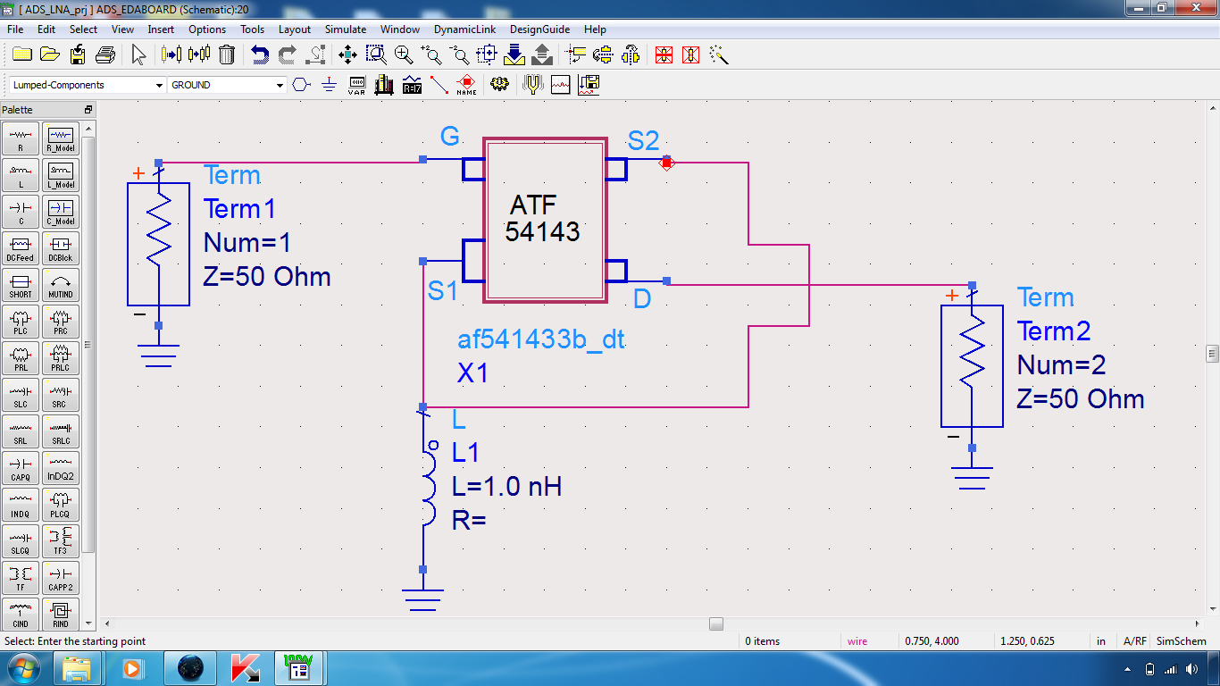
I attached the below figure, in that figure I want to make connection from S2 to S1 ( source to source of transistor) without connecting drain of the transistor(like jumper). In the below figure, there should be connection between S2 and S1 ( source to source of transistor), but there should not be any connection between S2( Source one terminal) to D( drain) and D( drain) to S1.How to make this connection, what I have to use between S2 and S1 to skip the connection of Drain in ADS2009( Advanced Design Systems 2009).


Looks like U got the connections right as u said..!! What is the confusion ??
 
Dear Sir,
If we connect as shown in the diagram, will it work. I want , there is no connection from S2 to D(drain ) and D to S1. But there must be connection between S2 and S1. What I have shown , will it work , there is no connection from S2 to D and D to S1.
 

The wires are running cross to each other but there is no connection. There would be a node created if there was any connection.. If U r still doubtful, then run ur wire around the space after ur Term2 and connect as u wish..!!
 
You can draw wires that cross other objects including other wires all the time without then connecting together. Only if you add a vertex to a wire that is on top of another wire will they become connected. There are easy ways of telling if two crossing wire are connected in ADS.

Firstly if you select any wire it becomes highlighted. If the highlighting passes over the point where the wires cross and highlights the selected wire both sides of the crossed wire then it is not connect. If the highlighing stops at the point where the wire cross it is connected at that point.

Secondly when two wires are connected, ie three or more wire segments are joined at a single point, it creates a wire tee junction and draws a small blue box, similar to a component pin but a slighly different blue colour.

See the image attached below. The first part is a copy of your circuit and the two crossing wire are not connected. The middle version of the circuit when I added the S1-S2 wire I paused at the point where the wire I was inserting crossed the drain wire and I then added the second section of wire to complete the connection. In this case the two wire are now connected and you should be able to see at that crossing point there is a blue dot. This is indicating the connection.

If you want to be absolutely sure that there is no connection then you can do as SpaceDust said and simply draw the wire around the outside the schematic, around the ground and Term symbols, to make the connection or simply not draw the wire at all but use a wire/pin label to create a named connection. Use the menu command Insert > Wire/Pin Label... or the equivalent button on the second toolbar to enter a unique name, I used "Source" and while the UI is still open click on the S1 wire and then the S2 pin on the device and you should see the label annotation appear and the pins turn blue in colour to show they are connected. See the third example in the image below. When you simulate the schematic these two pins will netlist as if they are connected together but there is no explicit wire on the schematic.

WiresLabels.png
 
Status
Not open for further replies.

Part and Inventory Search

Welcome to EDABoard.com

Sponsor

Back
Top