Continue to Site

Welcome to EDAboard.com

Welcome to our site! EDAboard.com is an international Electronics Discussion Forum focused on EDA software, circuits, schematics, books, theory, papers, asic, pld, 8051, DSP, Network, RF, Analog Design, PCB, Service Manuals... and a whole lot more! To participate you need to register. Registration is free. Click here to register now.

Circuit configuration with both voltage and current source

Status
Not open for further replies.

Teszla

Member level 2
Joined
Jun 6, 2013
Messages
45
Helped
1
Reputation
2
Reaction score
1
Trophy points
1,288
Activity points
1,556
attachment.php


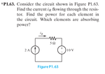
I wonder how this circuit configuration is possible. We have a voltage source of 10V, which (according to it's terminals) would induce a current in the counter-clockwise direction. Together with the resistance that would be a current of 2A counter-clockwise. However, we also have a current source which induces 2A in the other direction. Why doesn't these two cancel each other out?

Apparently the voltage source can also absorb power, which means that it's voltage would be in the other direction. But wouldn't it then be -10 V?

When applying KVL, the current source together with the resistance would be 2A*5Ohm=10V. For KVL to be correct, the voltage source then has to equal -10 V, wouldn't it? Might the "10V" written next to the voltage source be a misprint or is there any reason they didn't write a minus?
 

Attachments

  • circuit.png
    circuit.png
    17 KB · Views: 188

You are meaned to calculate the voltage across the current source. Why do you expect it to be zero? An ideal current source is forcing a current independent of the applied voltage.
 

Ok, the current source forces the current iR to be 2 A. But how is that compatible with the voltage source being 10 V? Shouldn't the voltage source be -10 V?
 

No, it's clearly said to be +10V. That's the starting point for your calculation.
 

Ok, I accept. The voltage over the resistance will also be 10 V, so that must mean the voltage over the current source has to be -20 V?
 

The voltage over the resistance will also be 10 V, so that must mean the voltage over the current source has to be -20 V?
You assumed that negative terminal of voltage source is GND,so positive terminal is at 10 V.You've calculated the voltage drop across R to be 10 V.So the voltage across current source is ____ (definitely not -20)??
 

What do you mean? I applied KVL, which says that V1+V2+(...)+Vn=0, so here we have Vvs = 10V, Vrs = 10 V, so in order for the equation to be correct the remaining voltage Vcs must be -20V?

Vvs + Vrs + Vcs = 0

10 V + 10 V + -20 V = 0
 
  • Like
Reactions: FvM

    FvM

    Points: 2
    Helpful Answer Positive Rating
@Teszla: Say,that you are applying KVL in clockwise direction.
Say,Vc is voltage at 1 terminal of current source & other is GND.The voltage drop(VR) across R is 10 V,voltage at positive terminal of battery(Vv) is 10 V.
So,in KVL, you are doing error in polarity of voltages in equation.

You seem to going in anti-clockwise loop in your KVL the polarity of current source,you're understanding it wrong although you're equation is correct.

Even,assume if your answer of -20 V is correct,your answer implies that current of 2 A is flowing from a node at -20 V to a node at 10 V !!!!!!!!!
Current always flows from a point of higher potential to a point of lower potential.
 
Last edited:

So what is the voltage over the current source?
 

There isn't but a misunderstanding about voltage annotation. -20V is correct when counting voltages in a clockwise loop (KVL analysis), +20V is the voltage of the upper current source terminal referred to lower terminal ("potential").

The original problem doesn't ask for voltage sign but power flow. I guess you can answer it now.
 

Status
Not open for further replies.

Part and Inventory Search

Welcome to EDABoard.com

Sponsor

Back
Top