alexan_e
Administrator
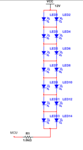
The led brightens is exactly the same when it has the same current no matter how it is placed.
Your previous test was with 40mA which was shared in the two leds that were in parallel so how do you compare the brightness of that to the brightness of 80mA for one led
Your previous test was with 40mA which was shared in the two leds that were in parallel so how do you compare the brightness of that to the brightness of 80mA for one led