PIC18F4550 is the one of most advanced controller form the Microchip Technology, mostly known for its USB functionality.
So Lets starts our USB Tutorial using PIC18F4550.
To make the things lot easier for newbie.
Compiler Used :- MikroC for PIC v5.30
Simulation Software :- Proteus ISIS
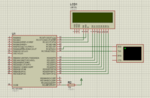
The Basic Circuit Diagram is as follow to achieve this communication is as follow :-

USB is a much complex device to handle but mikroC's inbuilt function has made it really simple to use this.
So lets Start our Journey..
Open MikroC IDE
Click on Project --> New Project --> Next -->
Set these Parameters
Project Name -> USB_HID_TEST
Project Path -> "Provide the path with Respect to your choice"
Device Name -> PIC18F4550 (I am using this Controller)
Device Clock -> 48MHz (Although i am using a 20MHz Crystal on Board but by setting HS_PLL configuration bit i am getting 48MHz Oscillation)
Now time to write Code for USB HID Class but before doing so, you have to provide the VendorID, Product ID etc.
This can be done simple in MikroC.
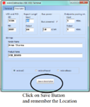
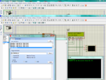
Now go to Tools -> HID Terminal
and set these values as shown in the following Snap.

After that you need to add this file into your Project.
Now go to Project --> Add Files to Project
Now its time to write the code, the program is self explanatory,
I have used the LCD in 8Bit mode, you can change the LCD part and use LCD-4Bit mode, or you can have the Library file from Mikroelektronika site.
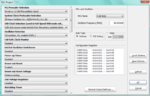
Now edit these Configuration Settings.

Just edit these settings only, leave the rest settings as it is.
Now Build the Project by clicking on the Build Project Button.
Now burn the hex file into your Hardware.
Now i will show you how this will run on your system.
Now open the HID Terminal, from tools menu of MikroC, later i will also post my own made software in Visual Basic 2010 to send data from PC to PIC using HID Class.
Now connect your hardware with PC.
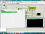
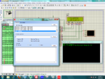
I am showing the simulation which i run on the Simulation Software.

See the LCD, then see the received data on Hyper-Terminal.
At this instant the USB is Enumerating.
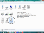
Enumeration Process is Successful, as you are getting USB_BOARD on HID Termina

The presence of USB_BOARD shows that's your board has been detected by your PC, you can confirm this my seeing the Device Manger Property.

Now its time to send some data from PC to PIC18F4550.
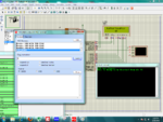
First i have to send 'S' through USB, this is just like a security check, if one doesn't send this character he/she will continuously get Authentication Fail.
In order to proceed properly you have to send 'S' first then proceed further.
The firmware is written in such a way, that the string sent by Hid-Terminal will be displayed on LCD.
First see if one send wrong character, like i am sending 'A' from HID-Terminal

Now one sends the Correct Code i.e 'S' form HID-Terminal

You will get Authentication OKAY on LCD.
After that i send PIC18F4550 string from HID-Terminal

and at last i send MY USB DEVICE")

Now time to Start Discussion on Visual Basic and USB,
In that tutorial we are sending data from HID Terminal from PC to PIC's LCD Display, now i will present a simple software developed in Visual Basic 2010 to send data from PC to PIC.
Due to some reasons i am not able to add more images, don't know why,
May be i had added to many images,
To see the next part of Visual Basic and PIC Tutorial refer this link.
https://sites.google.com/site/coolembeddedlaboratory/home/pic18f4550/visual-basic-and-usb
So Lets starts our USB Tutorial using PIC18F4550.
To make the things lot easier for newbie.
Compiler Used :- MikroC for PIC v5.30
Simulation Software :- Proteus ISIS
The Basic Circuit Diagram is as follow to achieve this communication is as follow :-
USB is a much complex device to handle but mikroC's inbuilt function has made it really simple to use this.
So lets Start our Journey..
Open MikroC IDE
Click on Project --> New Project --> Next -->
Set these Parameters
Project Name -> USB_HID_TEST
Project Path -> "Provide the path with Respect to your choice"
Device Name -> PIC18F4550 (I am using this Controller)
Device Clock -> 48MHz (Although i am using a 20MHz Crystal on Board but by setting HS_PLL configuration bit i am getting 48MHz Oscillation)
Now time to write Code for USB HID Class but before doing so, you have to provide the VendorID, Product ID etc.
This can be done simple in MikroC.
Now go to Tools -> HID Terminal
and set these values as shown in the following Snap.
After that you need to add this file into your Project.
Now go to Project --> Add Files to Project
Now its time to write the code, the program is self explanatory,
Code:
unsigned char Read_Buffer[16] absolute 0x500;
unsigned char Write_Buffer[16]absolute 0x510;
unsigned char num,flag;

void interrupt()
{
 USB_Interrupt_Proc();
 TMR0L = 100;             //Reload Value
 INTCON.TMR0IF = 0;       //Re-Enable Timer-0 Interrupt
}

//LCD 8-bit Mode Connection
sbit LCD8_RS at RC1_bit;
sbit LCD8_RW at RC0_bit;
sbit LCD8_EN at RC2_bit;
sbit LCD8_D7 at RD7_bit;
sbit LCD8_D6 at RD6_bit;
sbit LCD8_D5 at RD5_bit;
sbit LCD8_D4 at RD4_bit;
sbit LCD8_D3 at RD3_bit;
sbit LCD8_D2 at RD2_bit;
sbit LCD8_D1 at RD1_bit;
sbit LCD8_D0 at RD0_bit;

sbit LCD8_RS_Direction at TRISC1_bit;
sbit LCD8_RW_Direction at TRISC0_bit;
sbit LCD8_EN_Direction at TRISC2_bit;
sbit LCD8_D7_Direction at TRISD7_bit;
sbit LCD8_D6_Direction at TRISD6_bit;
sbit LCD8_D5_Direction at TRISD5_bit;
sbit LCD8_D4_Direction at TRISD4_bit;
sbit LCD8_D3_Direction at TRISD3_bit;
sbit LCD8_D2_Direction at TRISD2_bit;
sbit LCD8_D1_Direction at TRISD1_bit;
sbit LCD8_D0_Direction at TRISD0_bit;
// End Lcd8 module connections

char i;                              // Loop variable

void UART1_Write_Text_Newline(unsigned char msg[])
{
 UART1_Write_Text(msg);
 UART1_Write(10);
 UART1_Write(13);
}

void clear_buffer(unsigned char buffer[])
{
 unsigned int i = 0;
 while(buffer[i] != '\0')
 {
  buffer[i] = '\0';
  i++;
 }
}

//
void main()
{

  UART1_Init(9600);
  Delay_ms(100);
  UART1_Write_Text("USB Test Program");

  ADCON1 |= 0x0F;                    // Configure AN pins as digital
  CMCON  |= 7;                       // Disable comparators
  TRISB = 0x00;
  TRISC = 0x80;
  Lcd8_Init();                       // Initialize Lcd8
  Delay_ms(100);
  Lcd8_Cmd(_LCD_CLEAR);              // Clear display
  Delay_ms(100);
  Lcd8_Cmd(_LCD_CURSOR_OFF);         // Cursor off
  Delay_ms(100);

  Lcd8_Out(1,3,"PIC18F4550");                // Write text in first row
  Delay_ms(100);
  Lcd8_Out(2,3,"USB Example!");                // Write text in second row
  Delay_ms(2000);
  INTCON = 0;
 INTCON2 = 0xF5;
 INTCON3 = 0xC0;
 RCON.IPEN = 0;
 PIE1 = 0;
 PIE2 = 0;
 PIR1 = 0;
 PIR2 = 0;
//
// Configure TIMER 0 for 3.3ms interrupts. Set prescaler to 256
// and load TMR0L to 100 so that the time interval for timer
// interrupts at 48MHz is 256.(256-100).0.083 = 3.3ms
//
// The timer is in 8-bit mode by default
 T0CON = 0x47; // Prescaler = 256
 TMR0L = 100; // Timer count is 256-156 = 100
 INTCON.TMR0IE = 1; // Enable T0IE
 T0CON.TMR0ON = 1; // Turn Timer 0 ON
 INTCON = 0xE0; // Enable interrupts
 //
 // Enable USB port
 //

 UART1_Write(10);
 UART1_Write(13);
 UART1_Write_Text_Newline("Data is Ready to be Received from the PC");

 Hid_Enable(&Read_Buffer,&Write_Buffer);
 Delay_ms(2000);

 // Read from the USB port. Number of bytes read is in num
  start:
 while(Hid_Read() == 0);    //Stay Here if Data is Not Coming from Serial Port
 //If Some Data is Coming then move forward and check whether the keyword start is coming or not
 if(strncmp(Read_Buffer,"S",1) == 0)
 {
  Lcd8_Cmd(_LCD_CLEAR);
  Lcd8_Out(1,2,"Authentication");
  Lcd8_Out(2,8,"OK");
  goto loop;
 }
 else
 {
  Lcd8_Cmd(_LCD_CLEAR);
  Lcd8_Out(1,2,"Authentication");
  Lcd8_Out(2,5,"Fails!");
  goto start;
 }
 loop:

//Now Authentication is Successfull Lets Try Something else
//Lets Display the Data Coming from the USB HID Port to the LCD
 Delay_ms(1000);
 Lcd8_Cmd(_LCD_CLEAR);
 Lcd8_Out(1,1,"Received Data:-");
 flag = 0;

 loop_second:
 clear_buffer(Read_Buffer);
 while(Hid_Read() == 0)
 {
  if(flag == 0)
  {
   Lcd8_Out(2,1,"No Data");
   flag = 1;
  }
 }
 Lcd8_Cmd(_LCD_CLEAR);
 Lcd8_Out(1,1,"Received Data:-");
 Lcd8_Out(2,1,Read_Buffer);
 goto loop_second;
 Delay_ms(1000);
 Hid_Disable();
 Lcd8_Out(1,1,"HID DISABLE");
}
I have used the LCD in 8Bit mode, you can change the LCD part and use LCD-4Bit mode, or you can have the Library file from Mikroelektronika site.
Now edit these Configuration Settings.
Just edit these settings only, leave the rest settings as it is.
Now Build the Project by clicking on the Build Project Button.
Now burn the hex file into your Hardware.
Now i will show you how this will run on your system.
Now open the HID Terminal, from tools menu of MikroC, later i will also post my own made software in Visual Basic 2010 to send data from PC to PIC using HID Class.
Now connect your hardware with PC.
I am showing the simulation which i run on the Simulation Software.
See the LCD, then see the received data on Hyper-Terminal.
At this instant the USB is Enumerating.
Enumeration Process is Successful, as you are getting USB_BOARD on HID Termina
The presence of USB_BOARD shows that's your board has been detected by your PC, you can confirm this my seeing the Device Manger Property.
Now its time to send some data from PC to PIC18F4550.
First i have to send 'S' through USB, this is just like a security check, if one doesn't send this character he/she will continuously get Authentication Fail.
In order to proceed properly you have to send 'S' first then proceed further.
The firmware is written in such a way, that the string sent by Hid-Terminal will be displayed on LCD.
First see if one send wrong character, like i am sending 'A' from HID-Terminal
Now one sends the Correct Code i.e 'S' form HID-Terminal
You will get Authentication OKAY on LCD.
After that i send PIC18F4550 string from HID-Terminal
and at last i send MY USB DEVICE
Now time to Start Discussion on Visual Basic and USB,
In that tutorial we are sending data from HID Terminal from PC to PIC's LCD Display, now i will present a simple software developed in Visual Basic 2010 to send data from PC to PIC.
Due to some reasons i am not able to add more images, don't know why,
May be i had added to many images,
To see the next part of Visual Basic and PIC Tutorial refer this link.
https://sites.google.com/site/coolembeddedlaboratory/home/pic18f4550/visual-basic-and-usb