Continue to Site

Welcome to EDAboard.com

Welcome to our site! EDAboard.com is an international Electronics Discussion Forum focused on EDA software, circuits, schematics, books, theory, papers, asic, pld, 8051, DSP, Network, RF, Analog Design, PCB, Service Manuals... and a whole lot more! To participate you need to register. Registration is free. Click here to register now.

TV Transmitter

Status
Not open for further replies.

zxcsemaj

Junior Member level 2
Joined
Dec 27, 2022
Messages
20
Helped
0
Reputation
0
Reaction score
0
Trophy points
1
Activity points
140
Good day Everyone,

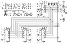
I am a ECE graduating student and I have a capstone/thesis project regarding to broadcasting and I found a TV Transmitter that can Transmit Audio and Video, I have a question what will be the value of those variable capacitor to have a frequency of 629.143MHz at Channel 40?

Or what should I do to make it tunable to a certain frequency?

Or do you have recommendations where I should simulate it because in multisim can't find other components there.

Or do you have a circuit for low power digital tv transmitter at least 1W for audio and video transmission? Thank you!

1W Transmitter Circuit.png
 

The schematic of the transmitter that you posted is from the book in the link below:

Try to get the book, because there is plenty of information how to build or to modify this transmitter.
 

The schematic of the transmitter that you posted is from the book in the link below:

Try to get the book, because there is plenty of information how to build or to modify this transmitter.
Actually, that's where I get this circuit diagram and the 1W Power Transmitter there comes with 2 variations just replacing the capacitor it will have 902MHz and 1300MHz, I'm confused if I will do the same to have the frequency to Channel 40 or I will modify the Inductor as well?
 

Both is possible. Presume you are aware of elementary LC circuit relations. 902 MHz caps need to be roughly doubled to arrive at 629 MHz resonance. The schematic seems to indicate capacitively loaded micro strip resonators in some places, resonance frequency is slightly different from lumped LC. I expect the book discusses the topic.
 

Both is possible. Presume you are aware of elementary LC circuit relations. 902 MHz caps need to be roughly doubled to arrive at 629 MHz resonance. The schematic seems to indicate capacitively loaded micro strip resonators in some places, resonance frequency is slightly different from lumped LC. I expect the book discusses the topic.
Thank you, Sir! I'll re-read the book again and study it. Last question is this circuit can receive to digital TV?
 

Presume you mean transmit digital TV? Popular standards, e.g. DVBT, DVBC are using complex QAM modulation schemes, require IQ modulator.
 

This circuit is too complicated and it will create so much trouble for a newbie.
If I were you, I'd use a TV Modulator IC and then a Power Amplifier. But the target is to learn RF discrete circuits, OK, you can change the oscillator circuit and abandon the double and tripler stages.
For instance I'd use a single transistor Collpits ( Clapp too ) varicap driven oscillator with a simple PLL ( MC145151)
The rest of the circuit can be used some modifications.
Can you guide me with that? Thank you in advance.
 

Last edited:


The IC is only suitable for analog TV. Digital TV is far more complicated, you have to generate baseband signals using mathematical functions and then mix them with a high frequency oscillator to shift them to your final frequency. It needs fast digital devices to generate the baseband and linear mixers and amplifiers to make the result usable.

Brian.
Thank you, Sir! Is it possible if I use digital to analog converter? Can't find a basic low power circuit for audio and video digital tv transmitter on google. Do you have suggestions or recommendations in the circuit?
 

Please review the comment about digital TV in post #6. Which digital TV source are you intending to transmit? You may want to google for Divital TV standards and QAM.
 

Please review the comment about digital TV in post #6. Which digital TV source are you intending to transmit? You may want to google for Divital TV standards and QAM.
I think its ISDB-T standard here in the Philippines.
 

It is very similar to my own analog TV transmitter although mine works at 1.3GHz. For ANALOG television it is fine but it will not work for digital TV. Sending digital TV is far more complicated. It isn't as simple as making a digital signal then feeding it to an analog transmitter. The extra information in a digital transmission cannot be sent on a single carrier like analog uses, you need a complex mix of AM, FM and PM called QAM or an even more complex system called OFDM. These signals are produced by mathematical algorithms, then have error correction bits added to them and finally sent to quadrature modulators, it is completely different to the method used in the schematic you posted.

Brian.
Thank you, Sir. How 'bout this one? I found on google it says that it is a DTT TV Transmitter do you think its working and need a programming/code to make it functionable? And also, what is the equivalent or replacement for TR391AV can't find on google. Thanks.
 

Attachments

  • schematic.jpg
    schematic.jpg
    274.2 KB · Views: 112

I'm not sure what that is except it has four AV input channels. It may be an SDI generator.
Where did you find the schematic? Even if it can produce a digital signal it would need up-mixing to final frequency.

Brian.
 

I'm not sure what that is except it has four AV input channels. It may be an SDI generator.
Where did you find the schematic? Even if it can produce a digital signal it would need up-mixing to final frequency.

Brian.
I found it here Sir, this link.
 

Status
Not open for further replies.

Part and Inventory Search

Welcome to EDABoard.com

Sponsor

Back
Top