Continue to Site

Welcome to EDAboard.com

Welcome to our site! EDAboard.com is an international Electronics Discussion Forum focused on EDA software, circuits, schematics, books, theory, papers, asic, pld, 8051, DSP, Network, RF, Analog Design, PCB, Service Manuals... and a whole lot more! To participate you need to register. Registration is free. Click here to register now.

Adjustable 280Mhz-434Mhz AM ASK transmitter

pabloortiz132

Newbie level 5
Joined
Jun 29, 2023
Messages
8
Helped
0
Reputation
0
Reaction score
0
Trophy points
1
Location
Badalona, Spain
Activity points
97
Hello,

I have 3 garage remotes, so I have recently started trying to create a single remote that can operate all 3 garage doors.
I have been using SDR to read the codes that they are emitting, and, using an arduino and a cheap 433Mhz transmitter module, I have achieved to replicate all codes to an acceptable degree of precision.
Both the remotes and my cheap module use ASK modulation.
I have also figured out the frequencies at which both the remotes, and my cheap transmitter module operate. The issue is that they are all different.
One of the remotes operates at 280Mhz, another at 433.92MHz, and another at 433.95Mhz. The cheap module operates at 433.6Mhz.

I am clueless as to how i could modify the cheap transmitter to emit at 280Mhz, or 433.9Mhz, or how to create my own circuit. I have looked into PLL's but the ones that can operate from 280-434Mhz are quite expensive. So I am currently trying to use an FPGA to generate the carrier waves (Tang Nano 9K).

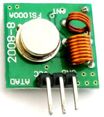
The cheap module uses a SAW resonator, and an inductor to increase the efficiency of the antenna.
There are no 280Mhz SAW resonators on the market.
Apparently the 433Mhz SAW resonators that are available, resonate at 433.9Mhz, so that also raises the question of why my module is emitting at 433.6Mhz: could I modify the circuit to adjust it to 433.9mhz? I will buy a few more modules from another provider who claims them to be 433.92mhz to test this.

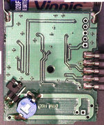
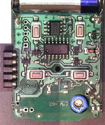
I have opened the 280Mhz remote, and it seems to be using an RC resonator circuit, with the resistor being a potentiometer, adjusted to produce 280Mhz, could an RC resonator resonate this fast? In that case i could try to replicate this, but I am quite sure an RC resonator wouldnt work for 433.9mhz so I would still have to figure that out.

So the question is, is the FPGA the right call, or is there a much cheaper way i could accomplish my goal?

Also, if you know a book I could read to get started on resonators and AM transmitters, I welcome any recommendation.

I attach:
- Picture of my cheap transmitter module
- Front and Rear pictures of the 280Mhz (adjustable) remote
 

Attachments

  • 433-MHz-RF-Transmitter-Module_0_0.jpg
    433-MHz-RF-Transmitter-Module_0_0.jpg
    52.9 KB · Views: 83
  • DTM-H6-Back.jpg
    DTM-H6-Back.jpg
    569 KB · Views: 81
  • DTM-H6-Front.jpg
    DTM-H6-Front.jpg
    641.8 KB · Views: 81

This transmitter needs only a 15MHz crystal and could set any frequency between 280MHz to 450MHz.

This device seems like it could be the right fit, I will try to acquire one and test it.

Thank you
--- Updated ---


This transmitter needs only a 15MHz crystal and could set any frequency between 280MHz to 450MHz.
I have tried to find the part, but it only seems to be available at Mouser Electronics, and they ask for 20€ shipping, so it wouldnt really be more cost effective than using the FPGA for its PLL, it cost about 20€ in aliexpress with shipping, and it can both emit the codes and modulate them.

I think the only cheaper way would be to somehow build an equivalent to my FS1000A module but for 280MHz (the biggest problem is finding a substitute for the SAW oscillator, and try other manufacturers of the 433.92MHz variant to see if i can achieve that frequency without modifications.
 
Last edited:
I have found someone that can help me buy the chip from Mouser, but looking at the datasheet, the minimum frequency of 280MHz may be unattainable:
The minimum frequency possible using a 15MHz oscillator, is
F(RF) = 15Mhz * (16 + 2.9536) = 284.304MHz

To achieve 280MHz, a 14.7729MHz crystal should be used, but the only one I can find is 14.318MHz. Would the chip work with a 14.318MHz reference crystal oscillator despite the datasheet announcing that the minimum possible is 15MHz? Maybe they rounded the frequency range?
I will try regardless as this seems to be one of my only chances of achieving 280MHZ OOK modulation, but would like some insight if possible.
 
I presume, the crystal oscillator is suited to realize advertized 280 MHz, but according to datasheet, the chip doesn't cover 280-434 MHz with a single crystal. You'd need to choose a different chip or switch the crystal.

I notice that you get cheap universal 280 - 868 MHz remotes on the market. They probably don't comply with radio regulations but your self designed remote neither will.
 
Bear in mind that most receivers, not all, use very simple receivers with quite wide bandwidth so the frequency may not have to be exact. From my own tests on 433.92MHz SAW oscillators in commercial products they could be anywhere between about 432MHz and 435MHz but they all operated the same receivers.

Brian.
 
Yes, the chip doesn't cover the entire range with a single crystal. The minimum and maximum frequency for a given reference crystal can be calculated as:
Fmin = max(280, Fxtal * (16 + 2.9536))
Fmax = min(450, Fxtal * (16 +12.0220))

For a 15MHz crystal, this range is 284.304-420.33 MHz
For a 14.318MHz crystal, it is 280MHz-401.218996 (Because the internal VCO can't reach 271.377MHz)

It is fine if i only use this module for 280MHz, I can use another, more standard, CC1101 module to achieve any other frequency I desire, only my grandma's garage still uses the original frequency, set before Europe agreed to use 433.92MHz as the small range standard in the 2000's.

My issue, is that the datasheet specifies the minimum crystal frequency as 15MHz, and I don't know if they just rounded those figures, or it strictly has to use a crystal in the 15-16MHz range.

Aside from that, the datasheet says the power amplifier output should be connected to an impedance matching network. I was thinking I could use the impedance matching + harmonics filtering network used in the Evaluation Kit. This application note says that it was optimized for the North American frequency range (288MHz-390MHz):

I don't know if using this would be counterproductive for emitting at 280MHz, nor how to modify it to be more efficient at 280MHz.
 
Bear in mind that most receivers, not all, use very simple receivers with quite wide bandwidth so the frequency may not have to be exact. From my own tests on 433.92MHz SAW oscillators in commercial products they could be anywhere between about 432MHz and 435MHz but they all operated the same receivers.

Brian.

I have tested my cheap FS1000A, SAW based emitter at the 2 locations that use 433.92MHz, and only one of them worked with the 433.6MHz my module produces. It uses remotes and a receiver from Aliexpress, while the one that didn't work, uses a receiver from a local company.
I have ordered a CC1101-based module that should allow me to emit at a more precise 433.92MHz, so I intend to use this module to emit at any frequency that I may need, from 300-915MHz, and the Maxim module only for 280Mhz.
 
I think (acording to datasheet, frequency programming) the math calculating the crystal is: 280/19 = 14.7368 MHz

However, I didn't find anywhere that 280MHz is a valid ISM band..
 
I think (acording to datasheet, frequency programming) the math calculating the crystal is: 280/19 = 14.7368 MHz

However, I didn't find anywhere that 280MHz is a valid ISM band..

First of all, bear in mind that in this datasheet they have a tendency to round numbers.
That said, when they say the minimum division factor is 19, it is in fact 18.9536 (Check Table 19).
The required clock for 280MHz would be 14.7729MHz, but the only crystal I can find that would satisfy the requirement is 14.318MHz.

I don't really care whether 280MHz is legal or not because i dont intend to emit at very high power, I just want to open the garage door at a distance of a few meters, and every other user of this garage has a 280MHz remote already, so if it was an issue, it would have already been addressed after 27 years of use.
 
I notice that 280 MHz is used for remotes and probably somewhere a legal band for this purpose. The fact that the band is included with said universal remotes seems to indicate this.

I don't see a reason why MAX7060 shouldn't work down to 14.7 MHz crystal frequency.
 
I notice that 280 MHz is used for remotes and probably somewhere a legal band for this purpose. The fact that the band is included with said universal remotes seems to indicate this.

I don't see a reason why MAX7060 shouldn't work down to 14.7 MHz crystal frequency.

Thank you, that reassures me a bit, I will try as soon as possible to see if it works. Any advice as to how i could modify the impedance matching + harmonics filtering network used in the evaluation kit to work better with 280MHz instead of the 288-390mhz range it was designed for?
My main concern is that this circuit would attenuate 280MHz, as it falls out of the range, I don't really need high efficiency as i only need a few meters of range
I attach the schematic and source.

PS: I would like to be able to fully understand how this circuit works, I am trying to learn about the concepts used here but they're quite new to me. Any resource I could use to learn more about them will be welcome.


1688376233904.png
 
Last edited:
If a transmitter can cover a wideband frequency range, this will not give permission to the user for transmitting everywhere. There are many cases like this, for chipsets, or even for full asembled transceivers. Manufacturers they don't care much about restrictions, because is not them who apply for transmitting frequency license, but the users.
280MHz could be a free band (actually nothing is for free today), but what I say, I cannot find anywhere written that actually it is.

The impedance matching network presented in Fig. 1 of the EV Kit, cover between 150MHz to 440MHz, so should be fine for 280MHz.
 

Attachments

  • 280.jpg
    280.jpg
    31.6 KB · Views: 58
If a transmitter can cover a wideband frequency range, this will not give permission to the user for transmitting everywhere. There are many cases like this, for chipsets, or even for full asembled transceivers. Manufacturers they don't care much about restrictions, because is not them who apply for transmitting frequency license, but the users.
280MHz could be a free band (actually nothing is for free today), but what I say, I cannot find anywhere written that actually it is.

The impedance matching network presented in Fig. 1 of the EV Kit, cover between 150MHz to 440MHz, so should be fine for 280MHz.
Thank you, that's very useful to know.
What software did you use to plot this? Is it open source? If not, is there a good open source alternative?

Thank you everyone for the help
 

LaTeX Commands Quick-Menu:

Part and Inventory Search

Welcome to EDABoard.com

Sponsor

Back
Top