Continue to Site

Welcome to EDAboard.com

Welcome to our site! EDAboard.com is an international Electronics Discussion Forum focused on EDA software, circuits, schematics, books, theory, papers, asic, pld, 8051, DSP, Network, RF, Analog Design, PCB, Service Manuals... and a whole lot more! To participate you need to register. Registration is free. Click here to register now.

[AVR] Transformerless power supply for ATMEGA16 microcontroller (Please help)

Status
Not open for further replies.

kushagra411

Newbie level 5
Joined
Mar 28, 2015
Messages
9
Helped
0
Reputation
0
Reaction score
0
Trophy points
1
Activity points
76
Hi Friends,
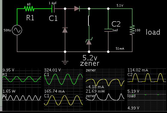
I want to use following circuit for power supply in atmega16 microcontroller.
I will also attach 7 leds to controller and one TSOP sensor.
Please tell me if it will work properly (when all leds are on) or not and
can i use it for long term(how reliable it will be).
Please help me guys. :smile:


ac2dctranz.JPG
 

Seems that will burn out the Zener diode, once you´re using a 47R in series with 240Vac, what means a Iz peak current ranging on the order of 7.1A. Other point is that even adopting this kind of power supply, a series resistor, for safety reason should be placed not at the Neutral side, but at the Line side.

[EDIT]

Correcting my previous post, ok, it´s a capacitive power supply, but I would recommend put the RC network at the Line net, as mentioned above.
 

Thanks for the reply.
What value R should i put with Line?
And can you please tell the current i will get with this circuit.
Its is working fine in simulator software but i wanted to know if my PIC will be safe with this or not.
:thumbsup:
 

i wanted to know if my PIC will be safe with this or not

The PIC can even be safe, but not you.:???:
As said before, you must to place the RC net at uper side of schematic.

What will define how much the PIC is safe is the proper functioning of the circuit above under rated specifications of these devices. In fact, what you should to check is whether the individual components of that power source are subject or not to stress conditions, both power (simulating current X voltage) as well as checking for example in the case of the diode, for the P/N selected, if the current passing through it will exceed some value of SOA datasheet chart. Have you simulated this power supply working with the full range of the expected load variation ?
 

Hi,

You say simulation is working ok.
Why not run your simulation with variable load to find out where the limit is.


Klaus
 

I totally understand that it has AC running though the board and no one is gonna touch the circuit.
Yes i tried to attach 3 LEDS simultaneously in parallel b/w VCC and GND but output was not good.
LEDS were not glowing continuously but flickering.
Though on implementing it was hardly noticeable but the C1 blew up after 5 hours of running.
That's why i want someone to please calculate the current output of this circuit because i don't know how to do that.
 

Hi,

If C1 blew up, then you didn't use the right one. It has notbing to do with load.

240V AC means +/- sqrt(2) × 240V of peak voltage at the capacitor.

Try a at least 300V AC X2 safety film capacitor.


Klaus
 

Your schematic shows a load of 10k. This calculates to 1/2 mA at 5V.
However from your description of your loads, I suspect you need a supply that provides several tens of mA.

I opened one of my previous simulations which resembles your schematic, and modified values so that it provides 5V at 50 mA.


R1 reduces inrush surge. You can use a 2W rating.

It's possible C1 is overburdened. It may be better to put a gang in parallel, so that you spread the burden.

It also may be better to install a full diode bridge. This utilizes power from both the positive and negative cycles. Your schematic only utilizes the positive cycle, and wastes the negative.
 
Status
Not open for further replies.

Similar threads

Part and Inventory Search

Welcome to EDABoard.com

Sponsor

Back
Top