Continue to Site

Welcome to EDAboard.com

Welcome to our site! EDAboard.com is an international Electronics Discussion Forum focused on EDA software, circuits, schematics, books, theory, papers, asic, pld, 8051, DSP, Network, RF, Analog Design, PCB, Service Manuals... and a whole lot more! To participate you need to register. Registration is free. Click here to register now.

Three phase delta configuration power factor calculation

Status
Not open for further replies.

zuirgham

Junior Member level 3
Joined
Mar 19, 2019
Messages
31
Helped
0
Reputation
0
Reaction score
1
Trophy points
8
Activity points
368
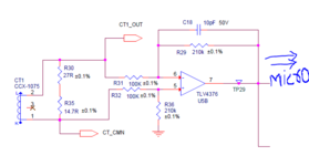
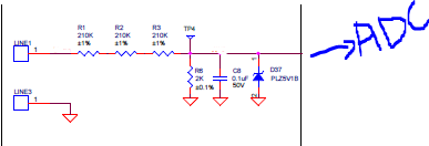
The power supply is from a generator (Three phase, delta configuration), as per requirement, need to measure active, reactive, apparent power. There is no need of Phase reversal as per customer. So i'm keeping that discussion aside. The previous version of board has a CT for current measurement for all three (L1, L2, L3), then passing through Diff amp and reading it directly inside controller. For voltage measurement, I'm dividing the voltage through resistor divider, and then passing through ADC(ADS7142), and reading in controller. FYI, Line 3 is used as a reference.
The next version of board has to calculate active, reactive, apparent power. To calculate all of that, need to calculate phase angle and then compute power factor. Couple of ideas i got while reading on web, one was to use a zero-crossing detector after voltage divider, and CT, and calculate Phase angle. Also, one of the papers suggested to go with Phase locked loops to determine phase angle. My questions are
1. Which approach is convenient, are there any circuits i can make use of ?
2. If zero crossing detector is used, where to put the detector?
3. I'm considering only two phases (L1, L2) as input, Will this be sufficient to calculate phase angle.
Guidance please on how to proceed for power factor computation.
 

Attachments

  • CT measurement.PNG
    CT measurement.PNG
    19.3 KB · Views: 118
  • Voltage measurement.PNG
    Voltage measurement.PNG
    8.4 KB · Views: 121

Solution
I think you should clarify what the actual input signals are, e.g. 3 or 4 wire power input. It should be also clarified if you expect a symmetrical 3 phase load or arbitrary phase currents. Futher are you are looking for displacement power factor only or total power power factor?
To start with, it’s a three phase three wire input system. Looking for displacement power factor for now. I was thinking to consider any two lines for computation...
If the generator is delta connected without neutral terminal, neutral is floating and phase-to-neutral voltage is undefined. You'll need to measure phase-to-phase voltage for your power measurement. Two differential measurements are sufficient. You won't necessarily need three current sensors because I3 = -I1 - I2.
You can also make a virtual neutral point, but should have three voltage measurements then, because you can't be sure about symmetry.

I have two comments about the suggested circuits.
1. Having the current sensor floating (you don't show if the CT_xxx terminals are connected otherwise) will pick up unnecessary high noise. Better ground it to the circuit common.

2. Your voltage measurement circuit must be able to process bipolar (AC) input voltage. Won't use an unipolar Z-diode as limiter. Do you plan to connect the measurement ground to neutral line? Other than protective earth, neutral must be expected to carry hazardous contact voltage. Better use a differential voltage divider, probably rather several Mohm than 600k resistance level, and difference amplifier. This way you are also able to sense phase-to-phase voltage.
I got lost in the middle trying to figure out the solution to calculate phase angle. Can you please be a little more specific on where to start off ?
I did not understand on how to compute the power factor. Can you please mention in steps, so that i understand it clearly. Thanks
 

I think you should clarify what the actual input signals are, e.g. 3 or 4 wire power input. It should be also clarified if you expect a symmetrical 3 phase load or arbitrary phase currents. Futher are you are looking for displacement power factor only or total power power factor?
 

Hi,

my approach:
use three resistors: One from each phase to a common star point.
use this as reference for your phase voltage measurements.

This gives you magnitude as well as phase.

For sure - if there are unsymmetries, it may cause measurement errors.

Klaus
 

I think you should clarify what the actual input signals are, e.g. 3 or 4 wire power input. It should be also clarified if you expect a symmetrical 3 phase load or arbitrary phase currents. Futher are you are looking for displacement power factor only or total power power factor?
To start with, it’s a three phase three wire input system. Looking for displacement power factor for now. I was thinking to consider any two lines for computation.. your thoughts and guidance..!!
 

Solution
Hi,

my approach:
use three resistors: One from each phase to a common star point.
use this as reference for your phase voltage measurements.

This gives you magnitude as well as phase.

For sure - if there are unsymmetries, it may cause measurement errors.

Klaus
I'm new to these 3 phases, I read your comment. Can you please elaborate a bit with circuit and blocks, so that its easier for understanding.
 

Hi,

This is a rather basic circuit. There is only one way to connect three resistors to create a star point.
please do an internet search "3 resistor star point circuit".

The voltage across each resistor gives you the phase voltage. (on a symmetric system)


Klaus
 

Status
Not open for further replies.

Similar threads

Part and Inventory Search

Welcome to EDABoard.com

Sponsor

Back
Top