Continue to Site

Welcome to EDAboard.com

Welcome to our site! EDAboard.com is an international Electronics Discussion Forum focused on EDA software, circuits, schematics, books, theory, papers, asic, pld, 8051, DSP, Network, RF, Analog Design, PCB, Service Manuals... and a whole lot more! To participate you need to register. Registration is free. Click here to register now.

Ds1307 RTC Power Problem with battery

Saeedk9574

Junior Member level 3
Joined
Nov 6, 2023
Messages
31
Helped
0
Reputation
0
Reaction score
0
Trophy points
6
Activity points
215
Hi everyone,
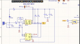
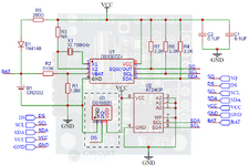
Whenever I apply voltage from source to the ds1307 RTC it works well but as soon as I connect it to CR2032 battery it gets stuck and Time does not work. I have checked the voltage of battery which is 3v but after resistance the provided voltage on ds1307 IC is about 1.5v. Accordingly, ds1307 needs minimum 2v. This is the circuit schematic diagram I took on the Internet and I did not design it by myself so I suppose the circuit is OK, but I do not know where the problem is.
 

Attachments

  • Screenshot (185).png
    Screenshot (185).png
    91.8 KB · Views: 148
Hi,

simple answer:
Read the datasheet and keep on the recommended schematic. Don´t rely on random schematics spread in the internet.

In detail: The resistors at the VBat pin of the DS1307 make no sense. I wonder what the "designer" thougt they would be good for.

Klaus
 
Not a sensible circuit. The voltages you measure are what I would expect with those values and it wont work as you have discovered.
I suspect the 3V3 at P6 was originally 5V but even then, adding extra load to the backup battery doesn't make sense. If nothing is drawing power from T3 (Testpoint 3 perhaps), remove R10, short out R9 and change R5 to something more like 10K.

Brian.
 
Hi,
but this is the circuit used in das1307 module, so I do not think they have put these components without reason.

So you think they know better than the manufacturer of the DS1307?

As a professional electronics designer - I can´t comprehend this behaviour to rather rely on on crappy cheap tinkerers schematics than the information of the original manufacturer.

I mean - simply the fact that it does not work - should result in some skepsis.
From my decades of experience: Do it like the datasheet recommends and it will work reliably.

Klaus
 
I agree, although I still think it is done in error but the modules your links point to just say "VCC" and I think it means 5V not 3.3V.
If you start with 5V, the diode and potential divider will produce around 3.3V at the battery, meaning no current is drawn from it while 5V VCC is present but if the 5V is removed, all it does is drain the battery faster.

Brian.
 
Hi,


So you think they know better than the manufacturer of the DS1307?

As a professional electronics designer - I can´t comprehend this behaviour to rather rely on on crappy cheap tinkerers schematics than the information of the original manufacturer.

I mean - simply the fact that it does not work - should result in some skepsis.
From my decades of experience: Do it like the datasheet recommends and it will work reliably.

Klaus
Thank you I will try with removing those resistances.
 
Another confusing point with the module schematic is that they have apparently a battery charging circuit installed for CR2032 lithium coin cell which is clearly forbidden.

I stop guessing about circuit purpose at this point. My suggestiion: either follow Maxim application notes or module instructions (if there are any).
 
I agree, although I still think it is done in error but the modules your links point to just say "VCC" and I think it means 5V not 3.3V.
If you start with 5V, the diode and potential divider will produce around 3.3V at the battery, meaning no current is drawn from it while 5V VCC is present but if the 5V is removed, all it does is drain the battery faster.

Brian.
It is OK with 3V as well as 5V. But I want it to continuous working by battery after disconnecting 3V. Based on datasheet ds1307 should work by battery after disconnecting 3v
 
Hi,
It is OK with 3V as well as 5V. But I want it to continuous working by battery after disconnecting 3V. Based on datasheet ds1307 should work by battery after disconnecting 3v
It´s not clear. Please use the same terminology as in the datasheet.

* It is Ok with 3V as well as 5V --> what does "It" mean in this case?
VCC is specified for 4.5V .. 5.5V.
VBatt is specified for 2.0V .. 3.5V.
As soon as VCC is applied, then the current drawn at VBatt is negligible.

But I want it to continuous working by battery after disconnecting 3V. Based on datasheet ds1307 should work by battery after disconnecting 3v
Which "3V"?
VCC is not 3V. It has to be 4.5V ... 5.5.V.
The battery is 3V, but if you disconnect the battery there is no 3V anymore.

Klaus
 
I wonder which battery is actually connected in your test. Charging circuit makes only sense if it's accu rather than CR2032.
--- Updated ---

I'm starting to understand the design considerations. In contrast to the schematic shown above, original "Tiny RTC" module uses LIR2032 rechargeable 3.6 V battery. 3.6V BAT voltage is above battery threshold, therefore they provided a voltage divider. Battery charging however doesn't work with 3.3V supply, datasheet is inconsistent in so far. I would use CR2032 and remove charging circuit and divider.
 
Last edited:
Hi,

It´s not clear. Please use the same terminology as in the datasheet.

* It is Ok with 3V as well as 5V --> what does "It" mean in this case?
VCC is specified for 4.5V .. 5.5V.
VBatt is specified for 2.0V .. 3.5V.
As soon as VCC is applied, then the current drawn at VBatt is negligible.


Which "3V"?
VCC is not 3V. It has to be 4.5V ... 5.5.V.
The battery is 3V, but if you disconnect the battery there is no 3V anymore.

Klaus
I do not understand why you make the issue confusing. The question is simple, why this RTC does not work with CR2032 battery, based on this designed schematic for module.
 

Attachments

  • DS1307-RTC-Module-Schematic.png
    DS1307-RTC-Module-Schematic.png
    94.1 KB · Views: 48
Hi,

The question is simple, why this RTC does not work with CR2032 battery, based on this designed schematic for module.
This question has been clearly answered multiple times by different posters.

I do not understand why you make the issue confusing.
You gave perfect informations.
It´s all my fault. Sorry for wasting your time. I will not bother you again.

Klaus
 
Hi,


This question has been clearly answered multiple times by different posters.


You gave perfect informations.
It´s all my fault. Sorry for wasting your time. I will not bother you again.

Klaus
And thanks for your perfect solutions.
Now I have all my answers.
 

LaTeX Commands Quick-Menu:

Similar threads

Part and Inventory Search

Welcome to EDABoard.com

Sponsor

Back
Top