Continue to Site

Welcome to EDAboard.com

Welcome to our site! EDAboard.com is an international Electronics Discussion Forum focused on EDA software, circuits, schematics, books, theory, papers, asic, pld, 8051, DSP, Network, RF, Analog Design, PCB, Service Manuals... and a whole lot more! To participate you need to register. Registration is free. Click here to register now.

DS1307 datasheet question

denny9167

Junior Member level 2
Joined
Apr 23, 2022
Messages
20
Helped
0
Reputation
0
Reaction score
0
Trophy points
1
Activity points
126
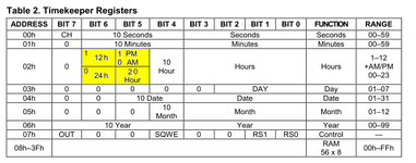
Don't know if its been asked, but the question is does bit 5 in the hour register toggle automatically when bit 6 is set and the chip is in 12 hour mode the datasheet doesn't say for sure, I have working code, and the clock is working in 12 hour mode, but the AM/PM isnt toggling every 12 hours like it should, and the "am_pm" variable is set to read bit 5. So could I have a faulty chip?

BTW it is one of those cheap modules!😁
 
Hi,

Where is the link to the datasheet?
Where is your "working code"?
Where is the DS1307 readout data?
BTW it is one of those cheap modules!
What does this mean?

Datasheet says:
Bit 6 of the hours register is defined as the 12-hour or
24-hour mode-select bit. When high, the 12-hour mode is selected. In the 12-hour mode, bit 5 is the AM/PM bit with
logic high being PM.
What is unclear?

BIT6:
LOW = 24h mode; HIGH = 12h mode

BIT5, in 12h mode:
LOW = AM; HIGH = PM;

And for sure .. it wouldn´t be a clock if it does not automatically update: seconds, minutes, hours, AM/PM, day ...

Did you follow datasheet rule:
The hours value must be re-entered whenever the 12/24-hour mode bit is changed.

Klaus
 
I simply asked if the bit toggles automatically Here is the line of code that flips the bit

hour = hour ^ 0x20;

the code flips the bit during editing but, in run mode nothing happens to bit 5.
There are at least two datasheets out there you want me to choose?????
 
I want to apologize, it is mostly my fault for posting this question, which I should have already known the answer. Most of the code I have seen that use adjustable time editing on RTC chips, toggle bit 5 at 1:00PM, particularly the code I was looking at, and that is where the problems begin, AM and PM don't toggle at 1:00 they toggle at 12:00:00! So 11:59:59AM doesn't increment to 12:00:00AM, but 12:00PM noon!! For some of You I know I'm stating the obvious, but C coders that write these files don't get the message, that is why many resort to software tricks to bypass bit 6 and bit 5 in the RTC register, because there is so much confusion on when the AM to PM transition, and vise versa occurs.
 
I couldn't post a link to some code , but it can be found at electrosome dot com.

Some have used this code in programming a ds1307 with PIC, and I decided to port it to XC8, but it wasn't working in 12 hour time, bit 6 wasn't properly set and bit 5 toggles were wrong, the below code properly writes to the hour address in the register.

if((hour & 0x1f) > 0x12)
{
hour &= 0x61;
}
else if((hour & 0x1f)== 0x12)
{
hour = hour & 0x72; // program register for 12 hour,setting bit 6 and bit 5
hour = hour ^ 0x20; // Toggle bit 5 at noon and midnight
}
}
 
Hi,

I don´t like the datasheet table.
1697802909782.png


isn´t it more like this?
1697803143260.png


Klaus
 

Attachments

  • 1697802885282.png
    1697802885282.png
    40.1 KB · Views: 35
My code will need to be changed if the hour is decremented of course.
--- Updated ---

Hi,

I don´t like the datasheet table.
View attachment 185616

isn´t it more like this?
View attachment 185618


Klaus
It is difficult to interpret
--- Updated ---

As long as one remembers to reset bit 6 and 5 for every hour change, when incrementing or decrementing.
 
I couldn't post a link to some code , but it can be found at electrosome dot com.

Some have used this code in programming a ds1307 with PIC, and I decided to port it to XC8, but it wasn't working in 12 hour time, bit 6 wasn't properly set and bit 5 toggles were wrong, the below code properly writes to the hour address in the register.

if((hour & 0x1f) > 0x12)
{
hour &= 0x61;
}
else if((hour & 0x1f)== 0x12)
{
hour = hour & 0x72; // program register for 12 hour,setting bit 6 and bit 5
hour = hour ^ 0x20; // Toggle bit 5 at noon and midnight
}
}
The hours value must be re-entered whenever the 12/24-hour mode bit is changed.
 
I couldn't post a link to some code , but it can be found at electrosome dot com.

Some have used this code in programming a ds1307 with PIC, and I decided to port it to XC8, but it wasn't working in 12 hour time, bit 6 wasn't properly set and bit 5 toggles were wrong, the below code properly writes to the hour address in the register.

if((hour & 0x1f) > 0x12)
{
hour &= 0x61;
}
else if((hour & 0x1f)== 0x12)
{
hour = hour & 0x72; // program register for 12 hour,setting bit 6 and bit 5
hour = hour ^ 0x20; // Toggle bit 5 at noon and midnight
}
}
One correction to securely set bit 6:

the line "hour &= 0x61; " needs to be "hour = 0x01 | 0x60;"
 
the line "hour &= 0x61; " needs to be "hour = 0x01 | 0x60;"
Whether you write "0x61" or "0x01 | 0x60" makes no difference. The compiler will optimize it to the same code.

But whether you write "&=" or just "=" makes a big difference.
The one is a "read modify write" instruction that keeps previous states of bits 1, 2, 3, 4, 7.
While the other sets those bits to zero.

And if I'm not mistaken, setting those bits to zero contradicts the rule that hours in 12h mode should be in the range of 1...12 (0 not included).

Klaus
 
Last edited:
I believe an additional line of will insure the bit 6 is properly set and the code has been tested and works.

C:
case 1:      hour= BCD2Binary(hour);
                                  if(!plus_button)hour+= 1;
                                  hour =Binary2BCD(hour);
                                   if((hour & 0x1f) > 0x12)
                                   {
                                        hour = hour & 0x61;  // This bitwise AND sets the parameters for the clock adjustment
                                        hour = hour ^ 0x20; // This bitwise XOR allows for bit 5 to toggle
                                        hour = hour | 0x40;  // This additional line of code insures that bit 6 is properly set.
                   
                                   }
                                   I2C_Write_DS1307(2, hour);
                                     break;

without the addtional line of code their is no guaratee that bit 6 is set, sometimes it will set and sometimes not.
 
Hi,

What is a "Binary2BCD" function? What is it suppsed to do? (I mean: the DS1307 already send it BCD coded..)
then .. it might be processed two times... Are you sure this works as expected? Did you check on all eventualities?

then:
Code:
hour = hour & 0x61;  // This bitwise AND sets the parameters for the clock adjustment
Why 0x61?
here you want to keep the sate of bit#6 .. but later you overwrite bit#6 with 1.

Code:
   hour = hour ^ 0x20; // This bitwise XOR allows for bit 5 to toggle
What do you mean by "allowes it"? --> you force it to toggle.

without the addtional line of code their is no guaratee that bit 6 is set, sometimes it will set and sometimes not.
Makes no sense at all.
If this makes any difference, then because of a different problem, like I2C bus timing ....

Klaus
 
Hi,

What is a "Binary2BCD" function? What is it suppsed to do? (I mean: the DS1307 already send it BCD coded..)
then .. it might be processed two times... Are you sure this works as expected? Did you check on all eventualities?

then:
Code:
hour = hour & 0x61;  // This bitwise AND sets the parameters for the clock adjustment
Why 0x61?
here you want to keep the sate of bit#6 .. but later you overwrite bit#6 with 1.

Code:
   hour = hour ^ 0x20; // This bitwise XOR allows for bit 5 to toggle
What do you mean by "allowes it"? --> you force it to toggle.


Makes no sense at all.
If this makes any difference, then because of a different problem, like I2C bus timing ....

Klaus
It increments the variable in binary instead of decimal.

I had issues after compiling, bit 6 would not set consistantly, a bug possibly not sure.
 
Hello!

The piece of code you submit indicates that you don't fully understand what an RTC chip does.
The RTC chip does the time keeping automatically. This means that if you hook a crystal to it, then
it works. The RTC (all chips I have used, some other may differ) works in BCD, which means that
you don't have to take care of converting yourself.
When you are using it:
I will assume all the hours less than 10 are straightforward because binary is the same as BCD.
If you read 0x10, it usually means 16 but it means 10 hours. You have to separate this in 2 digits,
possibly in ASCII.

Taking the first 0x10 example, the highest nibble (10s of hours) is
(val & 0x30) >> 4. // select the 2 bits of the higher nibble because it might be either 0x20 or 0x10.
And the second nibble is
val & 0x0F
If you read 0x16, then you decompose it as above to a 1 and a 6. If you want to display these
numbers, you make the ASCII code by adding 0x30 and that's it. Personally, I generate a time
string with methods like
char * RTC1307::MakeTimeString(uint8 h, uint8 m, uint8s) {.......} that you can also overload
with a few variants.
And if you want to write for instance 16 hours to register 2, then you separate 16 into a 1 and a 6,
and recompose the BCD value to (1 << 4) + 6 before writing it to register 2.
That's all. Don't touch bit 6 except at setup time. Define it as a constant so that you can remember
the setting in runtime code. The hours will be incremented either from 12 to 12 (12 -> 1 -> 2 ... 11 -> 12)
if you are in 12 hours mode, or 0 to 23 if you are in 24 hour mode.

By the way, you shouldn't have a case1, case 2, etc. You just separate the number you get,
that's it. If it's in 12 hour mode, then you check the AM/PM bit and you write AM / PM accordingly
to your LCD, period. If you are in 12 hour mode, then bit 6 will mean AM/PM and if you are in
24 hour mode, bit 5 will mean 20 hour in which case bit 4 will be 0.

That kind of chip is meant to solve all the RTC problems in the simplest possible way once for all.
Don't make it more complicated than it is, it does everything for you.

Dora.


I believe an additional line of will insure the bit 6 is properly set and the code has been tested and works.

C:
case 1:      hour= BCD2Binary(hour);
                                  if(!plus_button)hour+= 1;
                                  hour =Binary2BCD(hour);
                                   if((hour & 0x1f) > 0x12)
                                   {
                                        hour = hour & 0x61;  // This bitwise AND sets the parameters for the clock adjustment
                                        hour = hour ^ 0x20; // This bitwise XOR allows for bit 5 to toggle
                                        hour = hour | 0x40;  // This additional line of code insures that bit 6 is properly set.
                
                                   }
                                   I2C_Write_DS1307(2, hour);
                                     break;

without the addtional line of code their is no guaratee that bit 6 is set, sometimes it will set and sometimes not.
 
Last edited:

LaTeX Commands Quick-Menu:

Similar threads

Part and Inventory Search

Welcome to EDABoard.com

Sponsor

Back
Top