Continue to Site

Welcome to EDAboard.com

Welcome to our site! EDAboard.com is an international Electronics Discussion Forum focused on EDA software, circuits, schematics, books, theory, papers, asic, pld, 8051, DSP, Network, RF, Analog Design, PCB, Service Manuals... and a whole lot more! To participate you need to register. Registration is free. Click here to register now.

[SOLVED] Thermocouple (Pt1000) measuring issue

Status
Not open for further replies.

Abdul.Hadi

Newbie level 5
Joined
Dec 20, 2022
Messages
9
Helped
0
Reputation
0
Reaction score
0
Trophy points
1
Activity points
87
Hello I am having issues when reading the temperature values using pt1000. It seems to work properly till 30 degrees centigrade after that it doesn't respond properly. I am using lm358
IMG-20221031-WA0027.jpg

This is the circuit diagram I am using.
I can also provide the code if needed. I am working on this for the first time so please help me out.
Kind Regards
Abdul Hadi
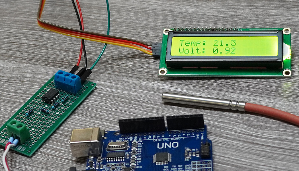
 

You don’t even know whether the problem is in your code or your hardware??? Post again when you’ve got some useful information.
 

I rather suspect the input voltage (pin 3 of the op amp) is taking the output beyond the limits of the LM358. Its output can't reach less than about 1.5V above ground or below supply. We don't know what supply voltage is being used but if it isn't relatively high the output will have simply max/min itself out.

Brian.
 

Hi,

Btw: A PT100 is no thermocouple.

I argree with the others.
We need to know
* what "it doesn´t respond properly" means
* expected temperature range
* expected output voltage range
* response time
* power supply voltage
* ...

It´s a minimalistic circuit with all it´s problems.

I recommend to use
* a more suitable RR IO OPAMP
* a power supply capacitor
* a low pass filter capacitor at the feedback

Klaus
 

I rather suspect the input voltage (pin 3 of the op amp) is taking the output beyond the limits of the LM358. Its output can't reach less than about 1.5V above ground or below supply. We don't know what supply voltage is being used but if it isn't relatively high the output will have simply max/min itself out.

Brian.
We are applying 3.3v
 

According to my calculation, the circuits achieves linear amplifier operation with LM358 over input voltage range of about 0.28 to 0.45 V, corresponding to -20 to 140 °C with Pt1000, limited by LM358 output voltage range of 0.1 to 2.1 V. Respectively, the problem is apparently not in the shown circuit.
 

LM358 can only go to 1.7V of 3.3 - so 1v6 max output ...
--- Updated ---

some local supply decoupling as well as 1nF from pin 1 to 2, may be of assistance .....
 

see code in this thread ....

Yes we used this code...
But we were achieving the right values according to the data sheet.

But when we increased the temperature from 30 to 50 it stopped responding.
 

If you feed A/D pin the V equivalent out of the LM358 when it stops working does A/D report
correct V ? Eg. way to eliminate the sensor and wiring from problem discovery.


Regards, Dana.
 

If you feed A/D pin the V equivalent out of the LM358 when it stops working does A/D report
correct V ? Eg. way to eliminate the sensor and wiring from problem discovery.


Regards, Dana.

Same constant voltage is displayed
 

Are your 1K and 10K R's precision ?

Your video shows the serial print values changing, does that occur for
non changing LM358 output ?

Is PT1000 flaky connection / wiring ?


Regards, Dana.
 

Hi

It´s not clear to me what exactly the problem is, what you expect and what you ee instead.
Until now you did not show your code.
Until now you did not show your circuit.

The video shows rising values for voltage and temperature.
What I can see: there is a jump from 0.99V to 1.44V. Unclear why.
Also unclear: How did you heat the sensor? It looks like it´s just lying on the table.
It does not "stop responding"
You claim a "constant voltage". I can´t see this.

If you are not able to give complete and useful informations .... nobody is able to help you.

***
A comment about the circuit and it´s web page:
* The circuit is not of high quality.
* the web page claims +/-0.5°C accuracy. This is simply is nonsense. If you have ideal PT1000, ideal resistors, ideal OPAMP, ideal power supply, ideal ADC ... and do an ideal match at 0°C and 100°C --> you still get about +/-1.2°C of linearity error. But each of them is not ideal thus add new errors, so realistically you have to excpect +/-3°C or worse.

There is so mach crap information on the internet.
Thus I recommend to use more reliable sources of informations. Every PT1000 manufacturer gives this, also many semiconductor manufacturers (datasheets, application notes), universities and reputable electronics developers.

Klaus
 

Hi,

I don't see his code.
It makes no sense to post someone else's code for debugging.
If your car doesn't work you don't bring your neighbour's car to the garage.

Klaus
 

Status
Not open for further replies.

Similar threads

Part and Inventory Search

Welcome to EDABoard.com

Sponsor

Back
Top