Continue to Site

Welcome to EDAboard.com

Welcome to our site! EDAboard.com is an international Electronics Discussion Forum focused on EDA software, circuits, schematics, books, theory, papers, asic, pld, 8051, DSP, Network, RF, Analog Design, PCB, Service Manuals... and a whole lot more! To participate you need to register. Registration is free. Click here to register now.

The role of feed back diode in ATX power

Status
Not open for further replies.

zereshki

Member level 1
Joined
Jun 15, 2008
Messages
39
Helped
1
Reputation
2
Reaction score
1
Trophy points
1,288
Activity points
1,627
hello.
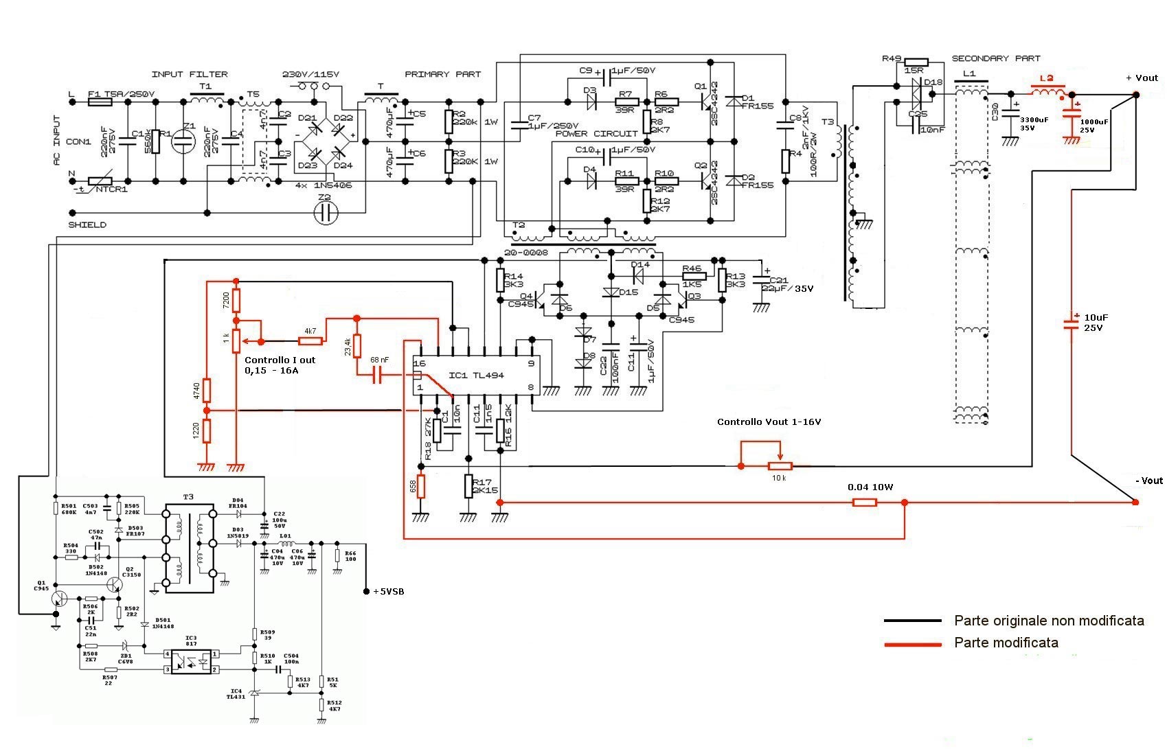
I want to modify ATX power supply and increase its output voltage.
In ATX circuits there is a 12v in addition to 5vsb for driving tl494 and other components. In most circuits there is a diode(some times series with a under 100ohm res) from main 12v rail to this 12v. When I remove this diode, circuit make noise like zzzzz.... .
At first I believed that the reason of using this diode is to help driving 12v supplier. But after removing diode there is no decreasing in 12v so this guess is rejected. I think some large spikes is happening but I do not have scope to check it. So I added a free running diode in 12v(I mean not main 12v rail) but no difference.

So some questions:
1- What is the role of this diode?
2- What is the reason zzzz sound?
3- Why some circuits have it and some not? (you can check it from :http://danyk.cz/s_atx_en.html)
4- and most important question how to remove this diode without any problem?

thanks
 

1- What is the role of this diode?
This diode is the path through the control system power itself. My guesses about its use is the following: if the power to the control circuit comes from before the output power rectifier (connected direct to the transformer), you need to use a diode. It's the SMPS principle of operation to get DC output voltage. But if the power comes from after the output power rectfier and before the series inductor, my guess is that when the load is opened while the supply is running, this inductor will revert the voltage across its terminals, and a negative voltage will appear at the point where you are feeding the control circuit. This would burn it. Using a diode, it will block this reverse voltage.

3- Why some circuits have it and some not?
I saw one circuit that did not use this diode, but the connection point was after the series inductor, so the reverse voltage would not cause trouble.

4- and most important question how to remove this diode without any problem?
When you removed it, you just did it or replaced it with something else? The power to the control system must come from somewhere, so just removing the diode will not work. And this maybe is the anser for [2- What is the reason zzzz sound?]. Sounds like 'zzzzzz' in SMPS may indicate a unstable system. The control system do not work properly with the lack of a good voltage supply.
 

thanks for your answer

if the power to the control circuit comes from before the output power rectifier.....
In all circuits anode of diode is connected after power rectifier, some circuits before series inductor and in some of them after that!!!!

This diode is the path through the control system power itself.....The power to the control system must come from somewhere
as I said there is another node in addition to 5v in standby supply that make 12v for control system. actually this voltage cause control system be able to start while main 12v rail not presented yet! and I have checked this voltage while diode was removed, and 12v was good and no decreasing happened. no change in operation frequency and main rail voltage. so I think the the role of supplier is rejected.

When you removed it, you just did it or replaced it with something else?
I want to disconnect them and replace with nothing. because I want to rise main rail up to 30 volt.


so I think the problem not solved yet.
 

Do you have the schematic of the supply you are working with? Maybe there's another biasing circuitty connected to this diode's 12V...
 

Do you have the schematic of the supply you are working with? Maybe there's another biasing circuitty connected to this diode's 12V...

Actually almost all power supply circuits are similar configuration. but after investigating the power pcb found that this one is like mine:
http://danyk.cz/s_atx01ad.png
http://danyk.cz/s_atx01s.png

:-?some confusing points:

1- these circuits do not have any feedback diode:
http://danyk.cz/s_atx01z.png
http://danyk.cz/s_atx01f.png
http://danyk.cz/s_atx01i.png

2- this circuit has feedback diode from main 12v rail to voltage control circuit and not tl494 supply:
http://danyk.cz/s_atx01p.png

3- this circuit has feedback diode from main 12v rail before power rectifier to supply 12v and there is not any other 5vsb!!! and 12v supplier,so at first time how tl494 start to work?!
http://danyk.cz/s_atx01a.png

4- no 5vsb and 12v supplier:
http://danyk.cz/s_atx01h.png
http://danyk.cz/s_atx01g.png
 
Let's start from the end of.
3- this circuit has feedback diode from main 12v rail before power rectifier to supply 12v and there is not any other 5vsb!!! and 12v supplier,so at first time how tl494 start to work?!
4- no 5vsb and 12v supplier:
It is the AT power source, not an ATX. They do not have the additional standby block and start work immediately after power is on. The inverter circuit is assembled on a self-excited, which is a positive feedback from the "mid-point" through the transformer there is a special winding or so. Working in the unmanaged mode, the inverter can be powered only control part of the power supply and the computer signal PowerGood bred in a state of deep reset.

1- these circuits do not have any feedback diode:
Control part is powered only by the standby block.
Actually almost all power supply circuits are similar configuration. but after investigating the power pcb found that this one is like mine:
It is standard ATX schema.
 

hello

Control part is powered only by the standby block.
in most circuits control part is powered by Vref of tl494 not standby block.

and main questions:
so do you know what is feed back diode role from main 12v rail ?
and why circuit make zzzz noise while this diode removed?
 

in most circuits control part is powered by Vref of tl494 not standby block.
I mean control part of inverter.
so do you know what is feed back diode role from main 12v rail ?
This is done to provide additional power to the control part when the SMPS is in operation. Cascade to control power switches, too, begins to consume power. Standby power unit may not be sufficient for the normal operation of the SMPS.
and why circuit make zzzz noise while this diode removed?
I think that this is not normal operation TL494. It has lost power and restored again.
PS Sorry for my English.
 

Standby power unit may not be sufficient for the normal operation of the SMPS.
I said as I measured, while diode is removed, there is not any drop in supply 12v that provided by standby circuit, so diode is not for providing supply voltage for tl494 IC.

thanks
 

Your multimeter integrates the input voltage, and you do not see the voltage drop if spike is short, but you hear it.

Zzzzz is about 300 Hz, the time for the meter to measure the standard method of dual-slope integrator is about 1s.
 
Last edited:

Your multimeter integrates the input voltage, and you do not see the voltage drop if spike is short, but you hear it.

Zzzzz is about 300 Hz, the time for the meter to measure the standard method of dual-slope integrator is about 1s.

At first I guess that may be some spikes is happening in 12v supply voltage (provided by standby circuit) so I replaced small filter cap in 12v (about 47uf) by 2200uf one but problem not solved.
actually I replaced divider resistor network by a 10k ohm pot for change the set point voltage. by decreasing the set point of voltage noise frequency increased.

actually I have thought about any reasons of this problem and try to solve it. but no change was happened. after all of them I presented it in forum.

thanks
 

See this thread.
atx_schema_03.jpg

https://www.edaboard.com/threads/230324/#post1210727
You might use some LM78XX for stability supply the TL494 in your SMPS.
 
Last edited:
  • Like
Reactions: FvM

    FvM

    Points: 2
    Helpful Answer Positive Rating
I saw this circuit before.I am doing the same work.It's not good idea to change feedback gain for variation of voltage because it effects on stability of circuit. so it's better to change set point on pin 2 of tl494.
In the modification of circuit can be seen that the feedback diode is removed, but it seems that the modifier of circuit has not problem that occurred for me. of course I test it(I mean removing feedback diode) in several atx power and the same noise was heard.

really I'm confusing with this problem
 

The modification in the above circuit effectively redesigns the TL494 circuit to achieve constant I/V operation. I didn't calculate the dimensioning but I presume it can be adjusted to work stable.

Beyond the scope of this thread, I wonder if modfication of ATX supplies is the best way to make your own supply.

I saw this circuit before.I am doing the same work.It's not good idea to change feedback gain for variation of voltage because it effects on stability of circuit. so it's better to change set point on pin 2 of tl494.
Quite funny. You don't have a clue what your modification of the original ATX supply does, but you "know" that the suggested modification affects stability. In fact, instability has a sound: "zzzzzz". (there are more sounds of course, also tones).
 
It's not good idea to change feedback gain for variation of voltage because it effects on stability of circuit. so it's better to change set point on pin 2 of tl494.
You're right, it's a better solution.
In the modification of circuit can be seen that the feedback diode is removed, but it seems that the modifier of circuit has not problem that occurred for me. of course I test it(I mean removing feedback diode) in several atx power and the same noise was heard.
As I said, I can assume that the backup source does not have the required output power for normal operation of the SMPS. The oscilloscope can clear this view, but as you say, you don't have it. Supply voltage TL494, as you know, up to 40V. You run the risk of blown the buffer transistors, if you leave feedback diode. Maybe try use LM7815 serial with this diode?
 
thanks for your answer

As I said, I can assume that the backup source does not have the required output power for normal operation of the SMPS

ok let calculate total consumption from 12v supply:

total consumption current = supply current of tl494 + internal NPN current + driver transistor current

supply current of tl494 = 10mA (max standby in TI datasheet,when NPN open @15v)
primary driver transistor current = worst case: assume driver transistor is in sat condition and one half of primary is short(we know it has more than short) = 12/1.5k(res @mid point of driver trans) = 8mA
internal NPN current = base current of driver transistor = 12/1.5k(minimum res value that I saw in several circuit to bias driver transistor) = 12/1.5k = 8mA

total consumption current = 10 + 8mA + 8mA = 26mA

Do you think a switching power supply can not provide this current?

- - - Updated - - -

thanks for your answer

As I said, I can assume that the backup source does not have the required output power for normal operation of the SMPS

ok let calculate total consumption from 12v supply:

total consumption current = supply current of tl494 + internal NPN current + driver transistor current

supply current of tl494 = 10mA (max standby in TI datasheet,when NPN open @15v)
primary driver transistor current = worst case: assume driver transistor is in sat condition and one half of primary is short(we know it has more than short) = 12/1.5k(res @mid point of driver trans) = 8mA
internal NPN current = base current of driver transistor = 12/1.5k(minimum res value that I saw in several circuit to bias driver transistor) = 12/1.5k = 8mA

total consumption current = 10 + 8mA + 8mA = 26mA

Do you think a switching power supply can not provide this current?
 

I specifically disassembled my SMPS, like yours. Voltage at pin12 TL494 is 21V standby and at runtime 23V. The capacitor in this network is at 50V, then why not at 25V.
 

I specifically disassembled my SMPS, like yours. Voltage at pin12 TL494 is 21V standby and at runtime 23V. The capacitor in this network is at 50V, then why not at 25V.

:shock: it's impossible, please make sure that you checked right filter cap!!!
as you checked standby power supply is more than main 12v rail (mine is almost the same). so diode is reversed bias!! isn't it?! so it can not be support for supply tl494.
 

I checked directly on pin #12 tl494.:lol:One of these diodes have the reversed bias always. First diode are the reverse bias in the operating mode and the second diode in the standby mode.
See at image.
8246742200_1369827148.png

In point A is a pulses with amplitude ~ 12V. Please note that after the diodes BD5 no filter capacitor, but there is a resistor R57. This part of the circuit works like a down-converter. The inductance L8 and capacitor C24 integrated input voltage and the resistor R57 are added to maintain the current in the inductor when closed diodes BD5. Voltage spikes when locking diodes BD5 rectifier diode D13.

In addition, you can see what came up Microlab.
 

Attachments

  • ATX_Microlab-5400X-1.pdf
    46 KB · Views: 83
Last edited:

Voltage at pin12 TL494 is 21V standby and at runtime 23V

by your comment I guess 12v(my power) is not enough for providing sufficient current through primary of driver trans. it cause power transistor do not switch well.(I guess, because for check it oscope is needed). I disconnected supply to tl494 and other,then get it from external power, by increasing from 12v (like on board power) to 23v, noise was disappeared. so there is three solution:

1-decreasing 1.5k res(midpoint of driver trans) and/or c945 biasing res
I decreased to half, for both of them, noise was decreased but by loading started again.may be half is not enough!!

2-change in divider resistors network of tl431.
it cause 5vsb increase too. but 5v is useful for digital

3-adding some turns to 12v node in secondary of stand by transformer
I don't test it yet

some comments on your circuit:


thanks
 

Attachments

  • ATX_Microlab-5400X-1.pdf
    74.7 KB · Views: 85

Status
Not open for further replies.

Similar threads

Part and Inventory Search

Welcome to EDABoard.com

Sponsor

Back
Top