Continue to Site

Welcome to EDAboard.com

Welcome to our site! EDAboard.com is an international Electronics Discussion Forum focused on EDA software, circuits, schematics, books, theory, papers, asic, pld, 8051, DSP, Network, RF, Analog Design, PCB, Service Manuals... and a whole lot more! To participate you need to register. Registration is free. Click here to register now.

Back-to-back converter burned down.

FEZAR

Newbie level 6
Joined
Oct 16, 2023
Messages
11
Helped
0
Reputation
0
Reaction score
0
Trophy points
1
Activity points
66
Hi everyone!
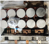
We had trouble with back-to-back converter that install on our wind turbine. Sometimes the converter burned down. The parts that usually were broken were IGBT modules one or two. We use FUJI and INFI converters inside our wind turbine. Unfortunately we don't have any idea about the trouble. We checked stuff like temperature condition, current by phases. We don't have opportunity to check the waveform of Vge, IC,VCE, controller output PWM. because we don't have digital tools for this. Could you please share your thoughts about this problem. Maybe you can give us advice about digital tools and diagnostic procedure. Thank you in advance.
 

Attachments

  • Stack converter back-to-back.PNG
    Stack converter back-to-back.PNG
    437.8 KB · Views: 25
you will never find the root cause unless you put some monitoring equipment on a running turbine to look at Vin to the converter, temperature of the heatsinks, etc

also - build up of dirt and dust over time followed by moisture can seriously upset power electronics.

also - your picture really shows nothing - except some dessicant (?)
 
Unfortunately, we don't have any clues about your design or flaws in design, setup or the components and the environment.

One cannot make any specific suggestions without a budget and scope of all the potential issues. But a datalogger with power, temperature, voltage and RPM are essential minimum parameters.

Did you review the design for instability modes? Surge protection? No-load over-voltage?
 
you will never find the root cause unless you put some monitoring equipment on a running turbine to look at Vin to the converter, temperature of the heatsinks, etc

also - build up of dirt and dust over time followed by moisture can seriously upset power electronics.

also - your picture really shows nothing - except some dessicant (?)
Thank you for your responce!

There are in converter we have special cooling system air and liquid with coolant. We hadn't any trouble with dusty because we have air filter. That about temperature grafic everything was ok before burning. We have only temperature and humidity monitoring only. But we don't know which tool we can apply for check PWM and gate Voltage for fully understanding how this the controller manage our IGBT . Thank you again
 
Unfortunately, we don't have any clues about your design or flaws in design, setup or the components and the environment.

One cannot make any specific suggestions without a budget and scope of all the potential issues. But a datalogger with power, temperature, voltage and RPM are essential minimum parameters.

Did you review the design for instability modes? Surge protection? No-load over-voltage?
He!Thank you for our interest.
We have full protection system there. It include DC-link voltage control, current control for each phases. Also we have tool for checking tempreture and humidity there , liqied and air cooling control. We had checked very thing after buurning case, but tempreture, humidity all the stuff were in normal condition. Current for all the phases was ok. DC- voltage also. We looking for digital or special device for checking PWM and gate voltage. I'm sure that our controller have the function but we don't know how we can get it from there.
 
Do you have grid data logger with sufficient time resolution to record surges and voltage dips?
Hello! Thank you for response. Yes we have DC voltage monitor, grid voltage monitor, and generator site voltage monitor. But there are 10 minutes data samples only. Should we use external equipment for monitoring?
 
You are asking about Failure Analysis and Root Cause on reliable brand converters like Fuji and Infineon. If their customer support cannot identify possible causes, then you need an experienced Test Engineer to review the production tests both at factory acceptance (FAT) and your on-site commissioning for fault-detection & protection "type" and "option" tests. I have Design, Test Eng and Production experience with power systems and there are too many questions to consider here.

But you do need a DVT or design Test Plan, based on the design specs and application requirements. Often sub-system DVT reports may have certain weaknesses measured by thermal margin, thermal runaway of current margin with thermal rise, and many parameters for fault detection before catastrophic damage and protection.

When I used to perform factory DVT tests, I would often raise the bar with non-destructive stress tests to determine if the protection method was adequate. Or determine what threshold might cause damage.

For example:

1. DC Fans start-stop have Hall sensors for commutation and when set for max efficiency may have a critical dead-band, where the fan may not start in one position, but then start after a small vibration disturbance to commutate the drivers forward. I once found this in 1% of fans from the top brand of fans. It was fixed by providing the supplier with an efficient test method so they could adjust their process control for Hall sensor positions.

2. PLT tests: power line transients are known and there are std tests for surge load, impulse tests, and thermal rise but who analyzes the design margin for passing or failing these tests?

3. Ambient exceptions: Did you experience any bad weather before these failures? Lightning etc.

4. IGBT Failure Modes: Have you identified the root cause of the thermal failure?
- overvoltage , overcurrent , grid instability,

In order to prevent these future failures, I would analyze the DVT reports and commissioning tests to ensure all the regulatory "type" and some "option" tests are used to validate the replacement sub-system modules and system.

Certainly, high-resolution event monitors would be important to use for SCADA systems like this but more importantly to perform these kinds of tests in a controlled manner is best with a planned DVT. Then for ongoing quality monitor use high-resolution impulse or exception monitors to capture these events rather than the benign data.
 

    FEZAR

    Points: 2
    Helpful Answer Positive Rating
You are asking about Failure Analysis and Root Cause on reliable brand converters like Fuji and Infineon. If their customer support cannot identify possible causes, then you need an experienced Test Engineer to review the production tests both at factory acceptance (FAT) and your on-site commissioning for fault-detection & protection "type" and "option" tests. I have Design, Test Eng and Production experience with power systems and there are too many questions to consider here.

But you do need a DVT or design Test Plan, based on the design specs and application requirements. Often sub-system DVT reports may have certain weaknesses measured by thermal margin, thermal runaway of current margin with thermal rise, and many parameters for fault detection before catastrophic damage and protection.

When I used to perform factory DVT tests, I would often raise the bar with non-destructive stress tests to determine if the protection method was adequate. Or determine what threshold might cause damage.

For example:

1. DC Fans start-stop have Hall sensors for commutation and when set for max efficiency may have a critical dead-band, where the fan may not start in one position, but then start after a small vibration disturbance to commutate the drivers forward. I once found this in 1% of fans from the top brand of fans. It was fixed by providing the supplier with an efficient test method so they could adjust their process control for Hall sensor positions.

2. PLT tests: power line transients are known and there are std tests for surge load, impulse tests, and thermal rise but who analyzes the design margin for passing or failing these tests?

3. Ambient exceptions: Did you experience any bad weather before these failures? Lightning etc.

4. IGBT Failure Modes: Have you identified the root cause of the thermal failure?
- overvoltage , overcurrent , grid instability,

In order to prevent these future failures, I would analyze the DVT reports and commissioning tests to ensure all the regulatory "type" and some "option" tests are used to validate the replacement sub-system modules and system.

Certainly, high-resolution event monitors would be important to use for SCADA systems like this but more importantly to perform these kinds of tests in a controlled manner is best with a planned DVT. Then for ongoing quality monitor use high-resolution impulse or exception monitors to capture these events rather than the benign data.
Thank you very much again!
This is very important information for me. We will consider the possibility of organizing a test program. This will require a lot of additional equipment and a separate test bench. The main thing here is expediency, because accidents happen once or twice a year on different wind turbines. And perhaps the cost of research will be too high. After all, we only operate the equipment, but we are not developers
 
I assume the warranty period has expired and the developers are no longer involved. If they designed it to survive the environmental stresses, for climate, electrical and mechanical, perhaps you must consult with them to estimate which specs were assumed and exceeded. Without a proper root cause analysis, you are hunting in the dark and need help from a hands-on consultant.

The Quality Mgr in charge must assess how much future losses and performance liability risks can be prevented by design changes to fault detection/ protection with secure remote monitors.

This includes test verification data for built-in fault detection/protection specifications from the developers and the OEM module factory support.

At a minimum multiple hottest spots need to be monitored internally with a DMM with Max hold capability on each phase. PLT monitors can record transient PowerLine events with thermal data on a Laptop only storing the events with thresholds defined.

Siemens, ABB, Huawei, Mitsubishi, Yokagowa and others have many resource options.
--- Updated ---

I cannot vouch for this person, but I know that PSCAD is a great tool for simulating faults on the grid such as Wind Farms. If you can imagine it, they can simulate it is their motto.

Also I cannot stress how inexpensive PDIV tests can be done by a design engineer and ongoing PD monitors are useful for random self-discharge transient events. These are like the canary in the mineshaft monitors for contaminated insulation monitors with high voltage. But for a technician, they can be very expensive without experience. https://www.linkedin.com/pulse/unperceived-partial-discharge-causes-igbt-failure-interference--1c/ When I discovered these tests, I found it useful to use a SW or AM radio between channels to detect PD.
 
Last edited:
I assume the warranty period has expired and the developers are no longer involved. If they designed it to survive the environmental stresses, for climate, electrical and mechanical, perhaps you must consult with them to estimate which specs were assumed and exceeded. Without a proper root cause analysis, you are hunting in the dark and need help from a hands-on consultant.

The Quality Mgr in charge must assess how much future losses and performance liability risks can be prevented by design changes to fault detection/ protection with secure remote monitors.

This includes test verification data for built-in fault detection/protection specifications from the developers and the OEM module factory support.

At a minimum multiple hottest spots need to be monitored internally with a DMM with Max hold capability on each phase. PLT monitors can record transient PowerLine events with thermal data on a Laptop only storing the events with thresholds defined.

Siemens, ABB, Huawei, Mitsubishi, Yokagowa and others have many resource options.
--- Updated ---

I cannot vouch for this person, but I know that PSCAD is a great tool for simulating faults on the grid such as Wind Farms. If you can imagine it, they can simulate it is their motto.

Also I cannot stress how inexpensive PDIV tests can be done by a design engineer and ongoing PD monitors are useful for random self-discharge transient events. These are like the canary in the mineshaft monitors for contaminated insulation monitors with high voltage. But for a technician, they can be very expensive without experience. https://www.linkedin.com/pulse/unperceived-partial-discharge-causes-igbt-failure-interference--1c/
Here is very useful advice from you. We may create digital model and try to imitate it. Thank you again. We have local company that provide it for us. And of course we'll try to use contact that you kindly provide for us.
 
When I discovered these PD tests, I found it useful to use a SW or AM radio between channels to detect PD. PD can sound like Lightning every minute maybe or every cycle as a ticking when it becomes worse.
--- Updated ---

Also look at other S/W from Manitoba Hydro

FACE provides faster solutions for determining the overall corona and field effects of high voltage AC, DC, or AC/DC hybrid transmission lines, such as:

  • Corona loss;
  • Audible noise;
  • Radio interference;
  • Magnetic and static electric fields;
  • Ionized fields, ion charges, and ion currents.
These are what can cause static partial discharges (PD) from accumulated charges from contaminants (dust etc in humidity) Early morning dew is a common time for PD or corona to harmlessly occur on ceramic bushings, but what effect does this have on control system for IGBT's?
 
Last edited:

    FEZAR

    Points: 2
    Helpful Answer Positive Rating
When I discovered these PD tests, I found it useful to use a SW or AM radio between channels to detect PD. PD can sound like Lightning every minute maybe or every cycle as a ticking when it becomes worse.
--- Updated ---

Also look at other S/W from Manitoba Hydro

FACE provides faster solutions for determining the overall corona and field effects of high voltage AC, DC, or AC/DC hybrid transmission lines, such as:

  • Corona loss;
  • Audible noise;
  • Radio interference;
  • Magnetic and static electric fields;
  • Ionized fields, ion charges, and ion currents.
These are what can cause static partial discharges (PD) from accumulated charges from contaminants (dust etc in humidity) Early morning dew is a common time for PD or corona to harmlessly occur on ceramic bushings, but what effect does this have on control system for IGBT's?
Hello! Good day !Here is incredible idea about SW and AM. We will definitely work in this direction as well. It's such a simple thought. But I am absolutely sure that this will help us find the problem and prevent it, of course, this will be one of the parts of our research planning. An integrated approach
--- Updated ---

When I discovered these PD tests, I found it useful to use a SW or AM radio between channels to detect PD. PD can sound like Lightning every minute maybe or every cycle as a ticking when it becomes worse.
--- Updated ---

Also look at other S/W from Manitoba Hydro

FACE provides faster solutions for determining the overall corona and field effects of high voltage AC, DC, or AC/DC hybrid transmission lines, such as:

  • Corona loss;
  • Audible noise;
  • Radio interference;
  • Magnetic and static electric fields;
  • Ionized fields, ion charges, and ion currents.
These are what can cause static partial discharges (PD) from accumulated charges from contaminants (dust etc in humidity) Early morning dew is a common time for PD or corona to harmlessly occur on ceramic bushings, but what effect does this have on control system for IGBT's?
Thank you!
 

LaTeX Commands Quick-Menu:

Similar threads

Part and Inventory Search

Welcome to EDABoard.com

Sponsor

Back
Top