Vermes
Advanced Member level 4
This project is to bring issue of stepper motors for everyone who want to learn more about control of those motors or create a motor with such a motor. More information can be found here:LINK.
Elements used:
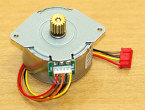
- M42SP unipolar stepper motor (or similar)
- ULN2003 – stepper motor driver
- DB25 connector
- cables
- tin
Schematic:
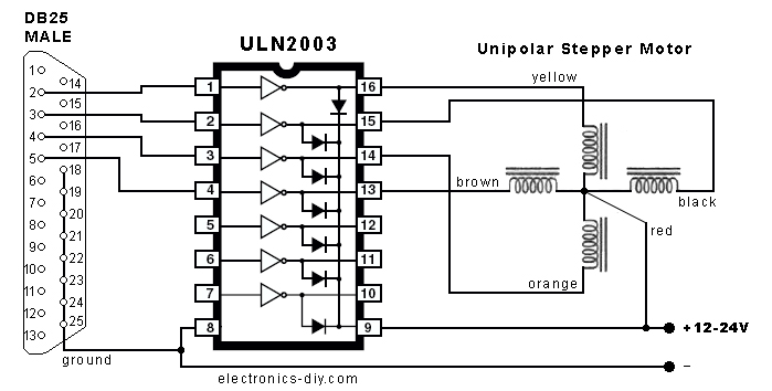
This controller is easy to made and allows you to control the stepper motor by LPT port.
Principle of operation:
Stepper motor differs from a normal DC motor, in which rotor rotates. In stepper motor, rotor changes its location at one step. The motor used in this project has 48 steps, what is precise enough for most users. In order to make the stepper motor move, the power supply should be given sequentially to the corresponding coils.
Connections of the stepper motor:

Unipolar motor should have 5 or 6 pins, depending on the model. If it has 6 pis as showed in the picture above, pins 1 and 2 should be combined and connected to 12-24Vdc power supply. Remaining pins a1 (yellow), b1 (black), a2 (orange), b2 (brown) should be connected to the driver ULN2003 as showed in the schematic.
Operation modes of the stepper motor:
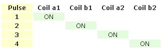
- Single stepping mode – the simplest model of motor control by giving voltage to the further coils (one coil at a time). Described here motor requires 48 steps so the motor can make a complete rotation. Making one step, the motor changes its position by 7,5 degree. The following sequence must be repeated 12 times for a full rotation.
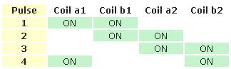
- High torque mode – torque is increased in this mode by applying power to two coils simultaneously.
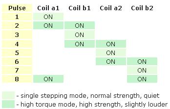
- Half step – the motor is stepped at a half step so it needs 96 steps to complete one full rotation. In this configuration, a single step changes the position of the motor by 3,75 degree. In the following picture you can see a combination of modes: 1 (bright green) and 2 (dark green).
Application for controlling the stepper motor from LPT port
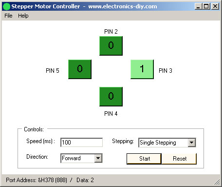
That application was created for education/test purposes. It allows you to choose the operation mode of the motor, change the speed and direction of rotation. In order to use it properly, you need to install Microsoft .NET Framework, which can be downloaded from: LINK.
The application can be downloaded from: LINK.
Link to original thread (useful attachment) – Kontroler silnika krokowego na porcie LPT