rickyjar
Member level 2
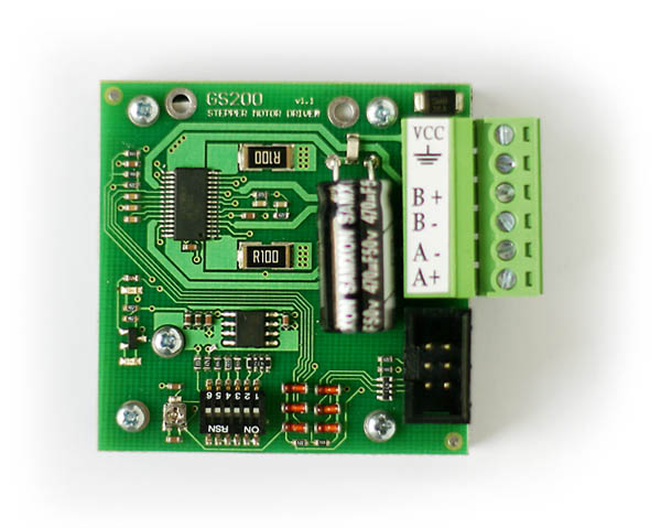
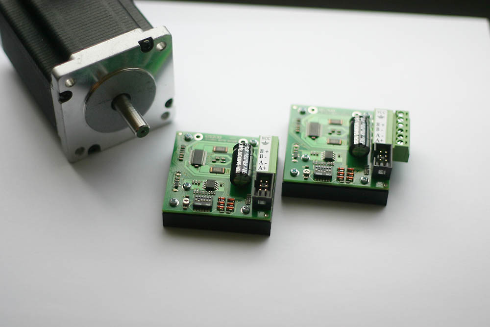
User “sokmarcin” presents his miniature controller of a two-phase bipolar stepper motor. The controller is based on the well known integrated circuit A3979 by Microallegro. Thanks to the integration of all the functions in one chip, the circuit requires only a few external elements.
About the construction:
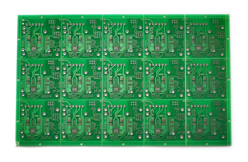
At first, the dimensions of the board were not as much a master o fan assumption as a master of necessity – wanting to ensure good performance of the circuit, the possibly short pathways are necessary, hence RC elements in 0603 casings were selected. It allowed the basic application of the circuit to be uploaded to rather a small surface of about 20 x 20 mm. At that moment, there was no choice but to adjust the rest of the elements and make a miniature controller.
As it was mentioned – the hart of the controller is the A3979 circuit, to measure current, low inductance resistors 0R1 in the casings 2512.
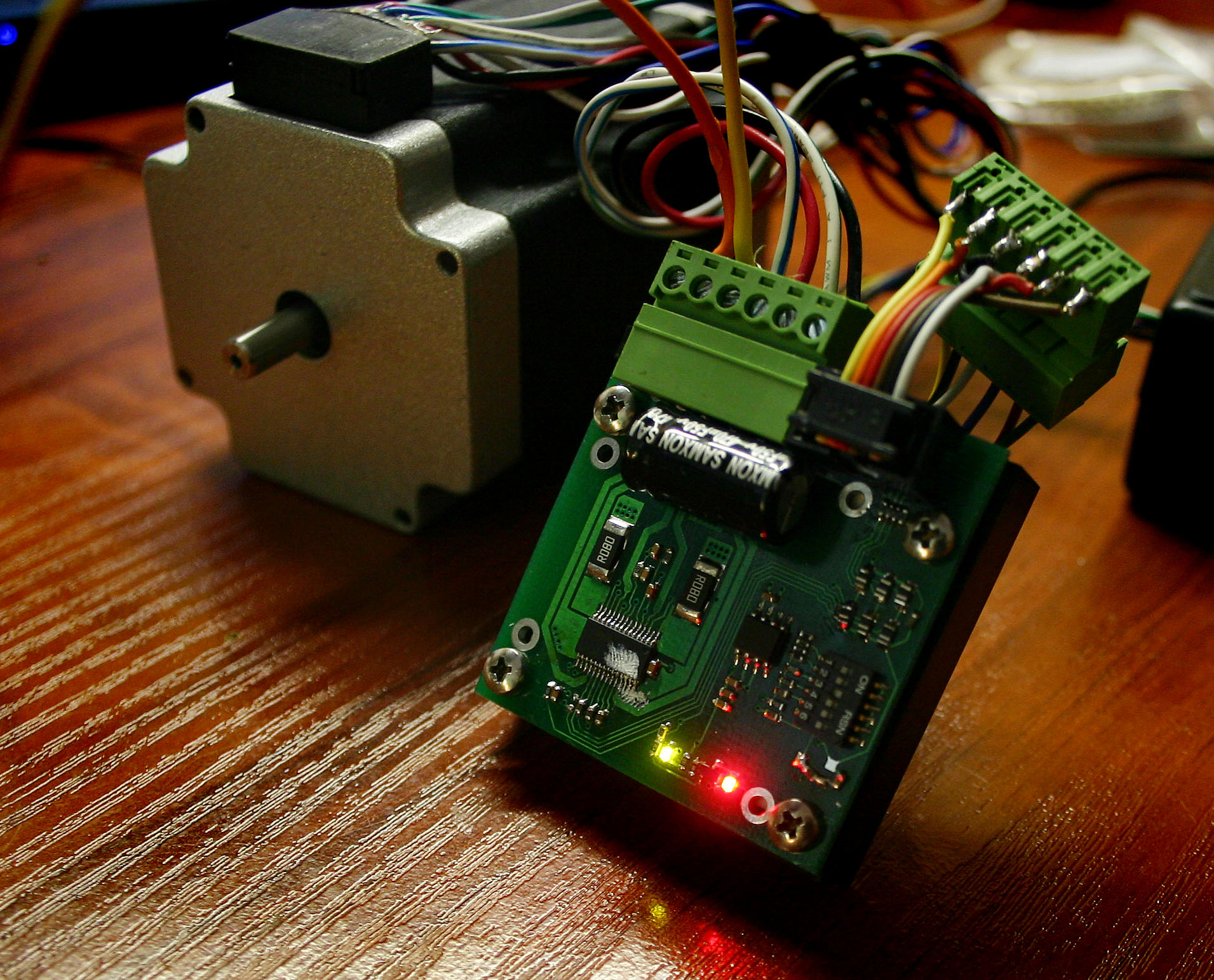
Additionally, the board has diodes signaling work progress, voltage regulators of logics supply (5 V), switch allowing selection of phase current and step division.
The controlling inputs were secured with diodes and serial resistor so that voltage on the pin of the circuit does not exceed the range 0-5 V (in practice -0.3 to 5.3 V).
The circuit possesses also a potentiometer allowing selection of extinguishing mode of overvoltages appearing while switching.
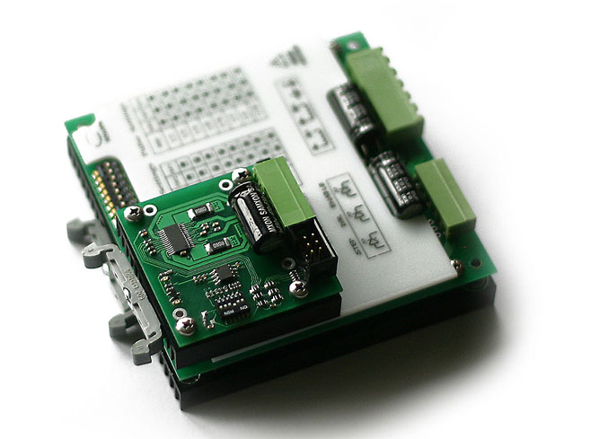
A heat sink 50 x 50 mm connected thermally to the board through a thermal silicone insert was used. The insert is place through all the surface of the board – thanks to this a relatively low thermal resistance of the PCB-radiator connector.
Parameters:
phase current: 0.2 A to 2.5 A;
power supply voltage: 10 V to 35 V;
step division 1, 1/2, 1/4, 1/16;
maximum frequency of STEP and DIR signal: 500 kHz.
Summary::
The controller works consistently, steadily and does not lose steps. The hot sink overheats with maximum current, however temperature does not exceed 70 C. With forced cooling, it was even possible to adjust phase current to about 3 A, but the controller was turning off after some time (thermal protection).
Pictures:

Link to original thread - Miniaturowy sterownik silnika krokowego