rickyjar
Member level 2
After modernizing, user Gizmoń’s plotter or even three-axial driller-milling machine controlled numerically, the stepper motor of the Y-axis started to behave like it had lost steps. It was caused by an insufficient braking torque of the motor - stressed accumulated during the movement were making the motor move back by one or two steps, when it stopped spinning. The controller in the form of four BDX33B transistors controlled with signals from the LPT port had no current resistance . When the coiling was left turned on, the motor warmed up very quickly and heavily, but the problem incorrect positioning of the device disappeared. Then, it was decided to introduce some modifications to the ready circuit that:
- will be added between the controlling inputs and the block with the power transistors;
- will ensure a half-stepper control in both directions for the motors of X and Y axes;
- will have any resistance of the current flowing through the motor, when it does not spin;
- will consist of modules ensuring the possibility of extending or modifying it;
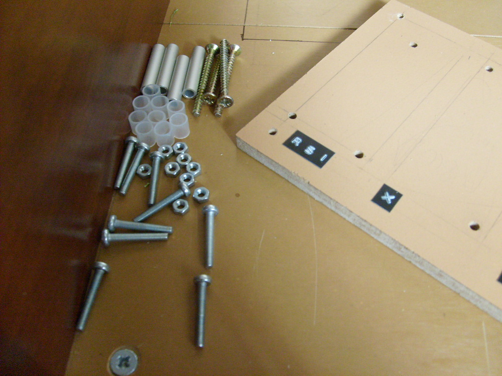
- will be hidden in the shelf under the counter of machine’s table, so it must be quite low.
The UCY74S405 circuit, which is the decoder of a binary system on one from eight, and the UCY74193 circuit, which is a four-bit reversible meter, were used. A two-direction circular meter with 8 outputs can be made of them. Negators with the Schmitt 7414N flip-flops serve to eliminate interferences and adjust the circuit to the controlling signals.
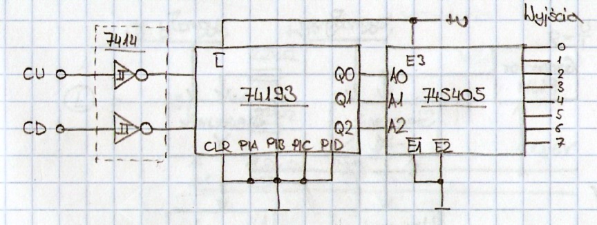
A matrix of 12 1N4148 diodes changing the signal one of eight into a sequence to control half-steps, is connected to the outputs of the UCY74S405 circuit. Behind the matrix there are four BC547 transistors enhancing and reversing the signal. Their interceptors can be directly connected to the bases of the power transistors.

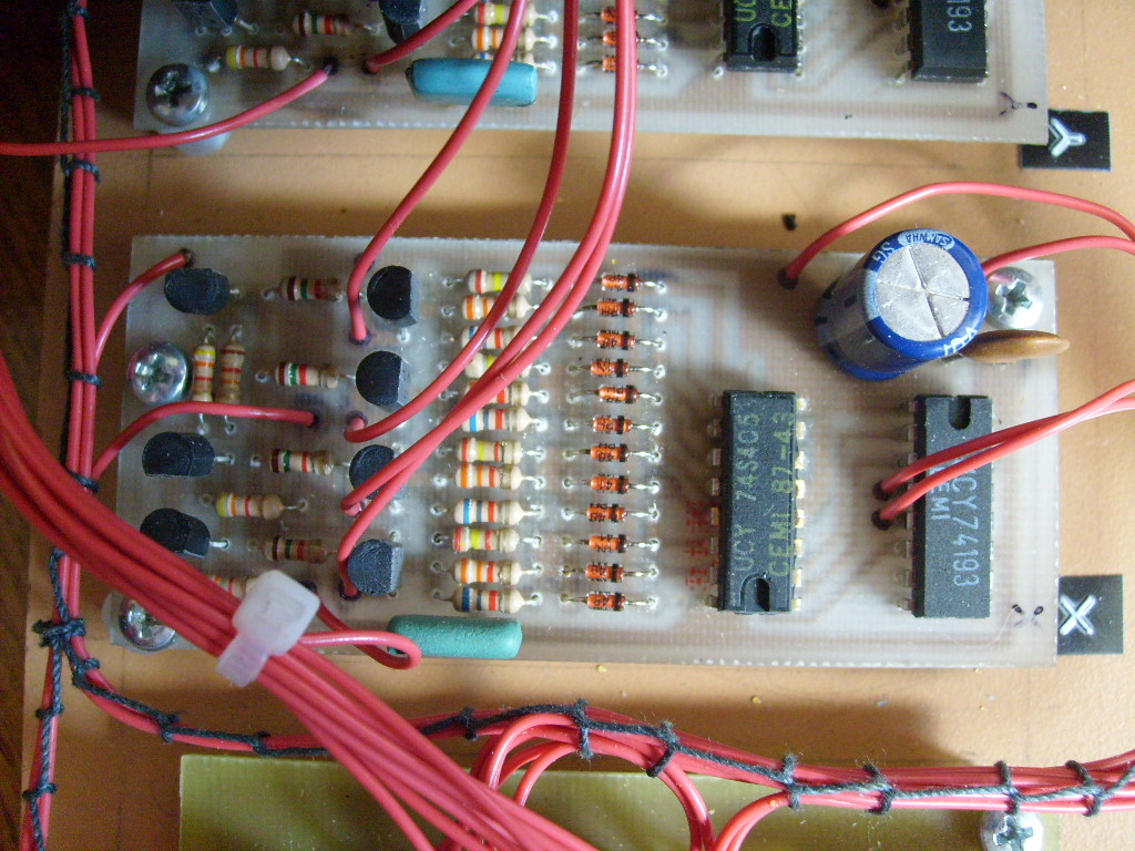
The current resistance consists of the NE555 circuit operating as a generator of rectangle-wave with adjustable duty cycle (below) and the elements marked with the frame in the above picture. The polarizing output voltage of the controller through the 1.2kΩ resistors can be constant, when on the NORM/PWM input there is a high condition or it can be controlled with the signal of the NE555 generator with a low condition. The NORM/PWM input is computer-controlled.
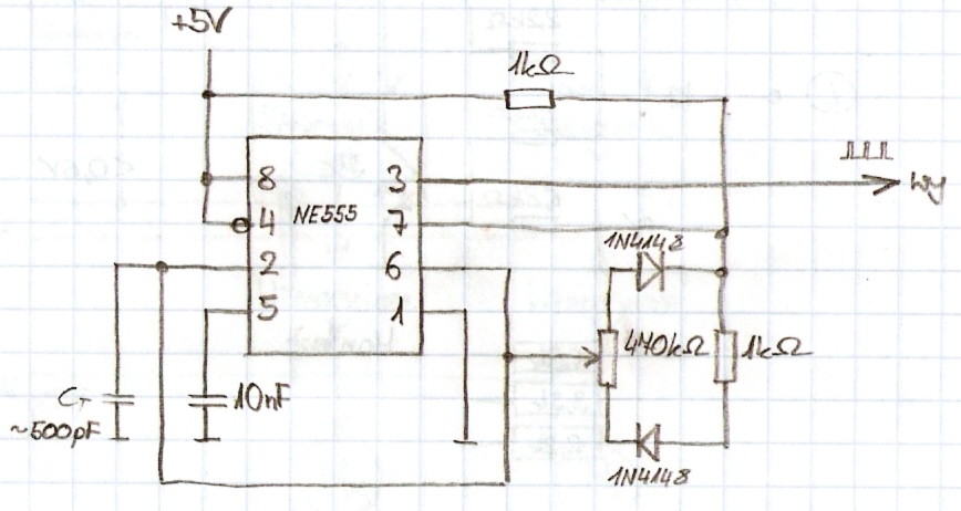
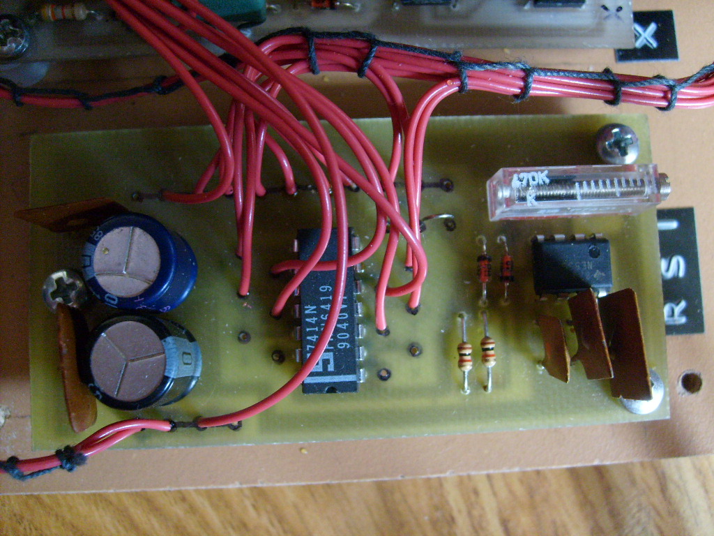
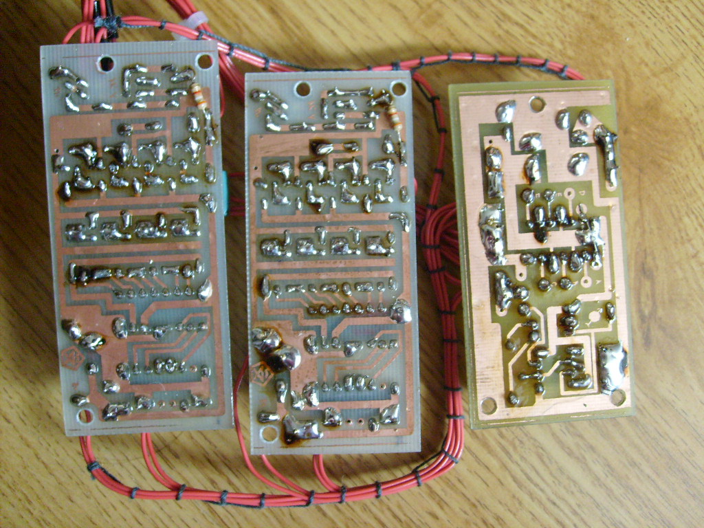
On the board of the generator there is a multi-rotary potentiometer to adjust duty cycle of signal and the above-mentioned 7414N circuit and capacitors on the supplying line +5V and +12V. The controllers constitute separate modules. The generator is shared by each.
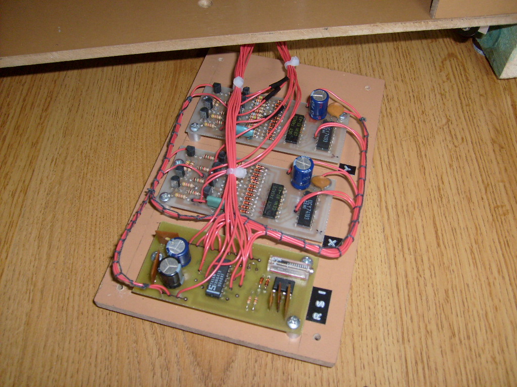
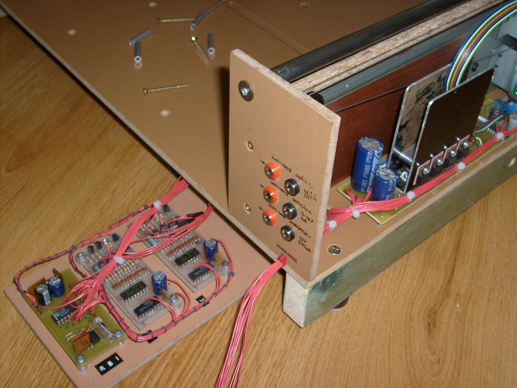
The boards were fastened to a rectangular shelf that then was mounted to the device. Some changes were introduced to the program – a dozen or so lines, whose tasks were taken over by new controllers, were replaced with several lines. Now each of the motors is supplied with full voltage from the power supply only during work, and for the rest of time low current preventing the roller from spinning accidentally.


Link to original thread - Tani i dobry sterownik unipolarnego silnika krokowego