Continue to Site

Welcome to EDAboard.com

Welcome to our site! EDAboard.com is an international Electronics Discussion Forum focused on EDA software, circuits, schematics, books, theory, papers, asic, pld, 8051, DSP, Network, RF, Analog Design, PCB, Service Manuals... and a whole lot more! To participate you need to register. Registration is free. Click here to register now.

Solar charge controller

Status
Not open for further replies.
Yes, you are absolutely correct. I also had the same thought because even the battery voltage was raised to 16V there was still no charging current. I will post the results with a good battery along with your suggested modifications (22uF capacitor across variable resistor).

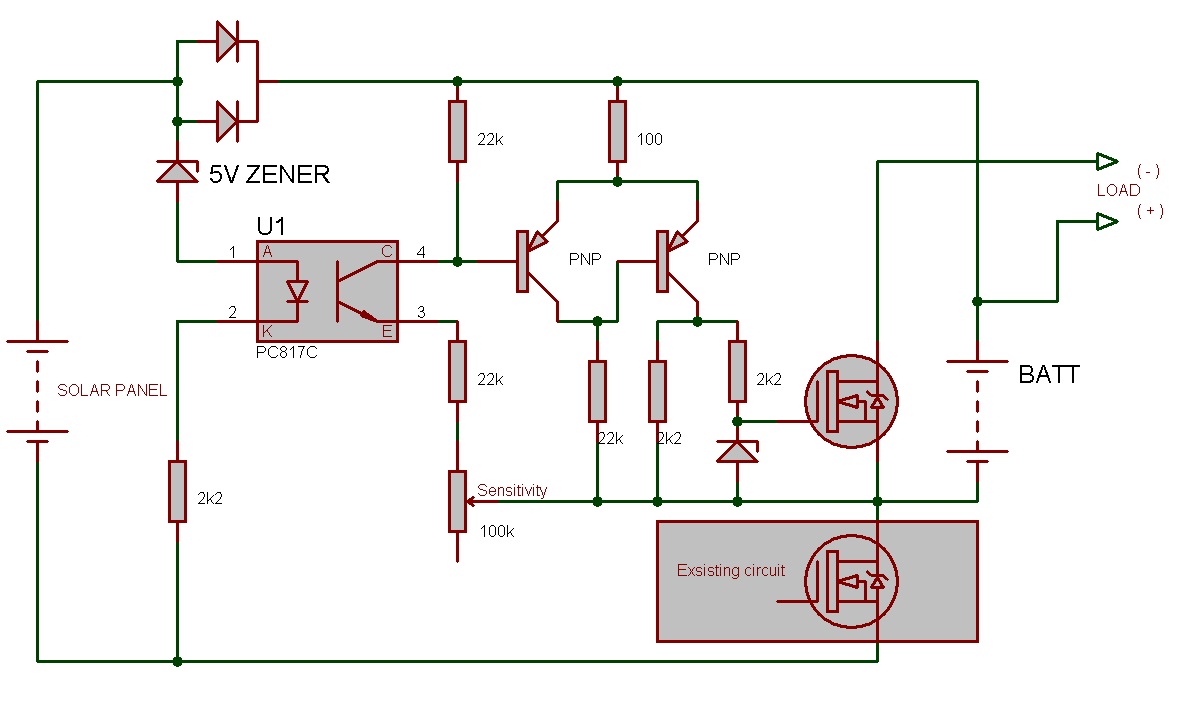
Can you please explain the operation of MOSFETs in the circuit I have recently added!!!

Charge Controller.png


Thanks!!!

- - - Updated - - -

Sorry I had not read your full text. Is the right side FET is used for current limiting? Should I include it in my circuit?
 

I think it is being used as reverse polarity protection.
 

The circuit is not practically good. Even battery is on charge permanently. There are excessive components, for example using relays where they can be easily avoided. For reverse protection, left side FETs will work. The right side FET circuit is similar circuit with different biasing but then if load is not battery then what is the purpose.
 

Thanks, ALERTLINKS. Really that circuit does not seems okay.

I got an another circuit, I am planning to use this circuit. This is microcontroller based charge controller. AND USES N-CHANNEL MOSFET. Using n-channel was my primary intention. They are cheaper & have low RdsON. (IRFZ44-0.024ohms, IRF9540-0.117ohms) so less heating.

solar_charge_controller_1c.gif

I want to change the design in two aspects. Firstly I want to add a switching circuit (either relay or MOSFET) so that the load after battery should only be connected when the solar voltage drops below certain voltage. (load will be ON only at night)

Second thing is to add reverse protection for battery so that in darkness the solar panel should not draw any current from the battery. Here again I am planning to use n-Channel MOSFET in ground path.

222.PNGMOSFETPN.jpg
 

so that in darkness the solar panel should not draw any current from the battery.
From the webpage,
"No diode in series with the panel?!?"

It should be noted that there's no "reverse polarity" diode in shown on the diagram as being in series with the controller to prevent the battery's charge from being applied to the panel when the sun is absent. As it happens, many panels have these diodes built in, anyway.

If, when you connect your panel (shaded from the sun, or in the dark) across your battery and you see more than a few 10's of milliamps flowing into the panel then you might consider adding a series diode to prevent this.
It require only a diode in series with solar panel. Reverse polarity protection is required where battery is disconnected often and there is a risk to connect it in a hurry with opposite polarity.
after battery should only be connected when the solar voltage drops below certain voltage
It is better to include these features controlled by microcontroller but otherwise it can be connected this way.

 
  • Like
Reactions: vbdev

    vbdev

    Points: 2
    Helpful Answer Positive Rating
Thanks, the circuit looks really good, I will try it. I can also use it in the previous circuit (using TL431). BTW that circuit is working fine now. The battery was faulty so no charging current & the solar panel voltage @16V appeared on battery terminals.

One more help please. I observed that the when using n channel MOSFET it does not heat as much but the diode needs a heatsink. So is that can I replace the blocking diode **broken link removed**.

nfet.png

One more thing, can I use the same MOSFET in your schematic as battery low cut-out?
 
Last edited:

Thank you ALERTLINKS, you have helped me a lot in this matter. I will check the circuit. I will also try using comparator chip so as to reduce the transistors.
 

@ALERTLINKS You have been of very much help here. I have a problem but don,t know how to do it easily, the costly solution would be to use a Uc with ADC, but I am reluctant to use it for now but if the demand is stringent then i would use a Uc certainly.
actually I have various types of system installed from 12v to 48v solar Panals (Voc from 21v to 84v) what I want here is to have such a system that when the solar energy is present the inverter should not be charging from utility electricity (in my Case WAPDA). such that the electricity bill could be reduced. I want to have a relay which disconnects the charger (MAINS) and just let go the solar charge by sensing the solar voltage and of suitable voltage from solar panel is found then switch off the relay.
 

suitable voltage from solar panel is found then switch off the relay.

This circuit will switch off the relay when there is near 15V from solar panel.
5523262600_1398369405.jpg
 

@ALERTLINKS thanks for the quick response, but how it would be done for 24v system and how did you calculate the 15v limit give me some hints so that I can adapt this system for various situations. does any NPN would do the job. and I also want this circuit to be run from solar panel with no voltage from battery or power supply
Thanks and regards.
 
Last edited:


For voltage adjustment, variable resistor and value of zener diode can be adjusted.
 

@ALERTLINKS, this is regarding your suggestion
**broken link removed**


The only missing feature that I need is to control the load as per the ambient light conditions. For that I am planning to use the fourth comparator.I will connect its +ve input to the reference voltage (2.5V) & -ve to a voltage divider network across the solar panel. Its output will be connected with the rightmost comparator output. Will it be okay?

I have some points, please clarify if I am wrong.

1. I think IRFZ44 is better than BUZ11 in terms of current rating as well as RdsOn.

2. We can use LM339 as its current consumption (@1mA) will be a fracion of the overall circuit consumption.

3. Is the MBR745 necessary at the output, what is its purpose?

4. Is capacitor of such a high value (1mF) needed at output?

5. Should I use 78L15 instead of the resistor & zener?

6. Do you find any problems in the circuit? I am asking this question because the author has mentioned the following..

It has been working fine for a year now (unlike my first attempt), although I suspect an unwanted state still occurs every now and again. Suggestions for improvement are welcome.

- - - Updated - - -

4. Is capacitor of such a high value (1mF) needed at output?

Sorry about this, I was confused it is 1000uF!!!
 
Last edited:

Ok but the PV voltages are not 24 volt and and 48v their Voc are higher then the the battery voltages, so should I select my zener values according to the Voc or the required voltage of switching. another problem is that I want to use only 12v relay in each case, so weather I should use regulators or dropping resistors.
 

Zener diode is according to battery. Make a step down circuit with LM2576HV.
https://www.hobby-hour.com/electronics/lm2576-step-down-switching-regulator.php
lm2576hv-adj-buck-regulator-schematic.png

It can work up to 60V. Feed this 12V to circuit and relay. Use zener according to battery. Only input on variable is directly connected to solar panel.


- - - Updated - - -

@vbdev. You are thinking on right path. I would consider using IRF3205 to support 20A-30A charging. In the present circuit it is considered to draw minimum current which is not necessary with big battery and high power. There is a resister missing which should be there.
res.jpg
 
Thanks, I am building the circuit & will post the results.
 

@ALERTLINKS! You can count my One thanks, I am also biluding the circuit containing the TL431 but as from the original website ( Select the solar panel in such a way that its amps capability is within the safe charging limit of the battery you intend to use.) can I use Mosfets like IRF3205 for higher currents or how to parallel them for high ampare.
 

Status
Not open for further replies.

Similar threads

Part and Inventory Search

Welcome to EDABoard.com

Sponsor

Back
Top