Continue to Site

Welcome to EDAboard.com

Welcome to our site! EDAboard.com is an international Electronics Discussion Forum focused on EDA software, circuits, schematics, books, theory, papers, asic, pld, 8051, DSP, Network, RF, Analog Design, PCB, Service Manuals... and a whole lot more! To participate you need to register. Registration is free. Click here to register now.

I want to switch solar panels between different systems, how?

Piet de Pad

Junior Member level 2
Joined
Feb 24, 2023
Messages
21
Helped
0
Reputation
0
Reaction score
0
Trophy points
1
Activity points
254
Dear Readers,

Inverters are switched off during a blackout and make that you have electricity on your roof while being without it in your home. This may not be as urgent where you live, but in countries like Mexico, blackouts are more common. In such a case, I want to be able to use the electricity from the solar panels to generate 120Vac for the house.

I want to connect the solar panel between two different systems, namely a micro inverter and a backup system. The switching between these two systems must be automatic. I assume modern solar panels can produce 550W STC at around 40V and 15A. How can we switch solar panel outputs was my question?

1) The first thing that comes to mind is a relay that can switch 15A - 40Vdc and is equipped with either SPDT or DPDT contacts. Such relays exist, but DC arcing makes them large and not cheap, at least from what I have been able to find.

2) Another possibility is SSR relays, but they only come in SPST configuration and have a voltage drop of 1..2V. They are suitable for string configurations but not for a single panel, as they result in significant power loss per panel, and they need cooling.

3) The remaining option is a MOSFET DPDT switch. MOSFETs come in various types and sizes, have a low RDSon, they can switch large currents at high voltages, and are not affected by arcing and contact aging. However, to my knowledge, such a switch does not exist as a ready-made product in the market.

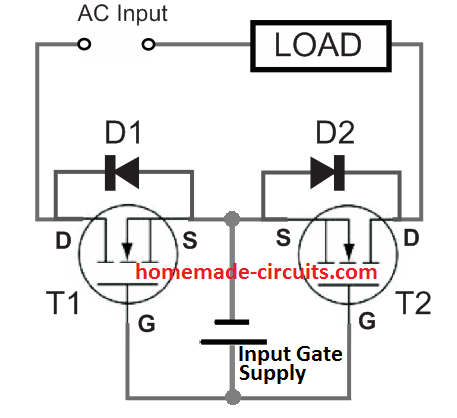
This is roughly the decision-making process I went through, and I have decided on the last option. I have designed a DPDT switch that can be controlled with a dry contact. Below, you can see the design that I tested in MultiSim Spice.

At the bottom left under Pan2, you can see schematically what the circuit on the right does. The circuit is essentially a DPDT switch consisting of two SPDT switches which are simultaneously controlled. The switch referenced "switch" in the schematic represents the dry contact that switches one of the two systems. T13 T14 T23 T24 control the gates of the MOSFETs.

This is my question:
Before I proceed with building this, I would like to know if there are people who have other or better ideas on how to make a solar switch. Perhaps people have experience with what I describe here. Maybe someone knows a product in the market that does this. If you know a product I would like to hear it. If you have better ideas, please let me know.

Hope to see some reaction, thanks.
Piet de Pad

Solar panel Switch DPDT.jpg
 
Hi,

some of your statements are not true, I think:
* SSR suffer from 1.2V voltage drop: --> There are MOSFET type SSRs that have rather low R_DS_ON
* MOSFETs are not affected by contatct arcing --> Arcs are generated by high voltage. This high voltage causes arcs in relay contacts but it also kills MOSFETs. There are ways to suppress/limit high voltage ... and thus is a benefit for both systems.

****

To your solution:
* I´m not sure whether a micro inverter (GTI) needs the input to be switched OFF in case of grid loss. It will switch OFF it´s output and thus I expect it to draw only minimal panel current. Check function/datasheet on this.
* To switch ON/OFF the panels you only need to switch one panel line. I´d switch the low side (minus) only ... with overvoltage protected MOSFETs
* you additionally need to selectively switch the load side, because it makes no sense (better say: it´s impossible) to supply the whole house from solar (limited power). You need to switch off heavy loads, like your washing machine...
* you must avoid to push back voltage from your inverter to a off_powered grid. It could be dangerous to people working on the grid.
* Load may draw a lot of inrush current (refrigerators for example). This may cause to stall your solar_only powered inverter. To be able to run these loads you need to have an extra energy storage - usually a battery. There are ready to buy solutions for [mains power, solar power, battery, inverter] backup systems.

Klaus
 
A more practical solution but marginally less effficient is to use the solar power to continuously run an inverter so you have two AC supplies normally (during daylight). Switching lower current AC is far easier than high current DC. With some planning you can also use the solar generated AC to feed in AFTER your electricity meter so you use home produced electricity to reduce your bill from the electricity company. This is how "grid tied" systems work, I've generated over 12 Megawatt hours of power here over the past ten years or so, reducing my apparent usage by over 12,000 units. Grid tied units are normally designed with anti-islanding circuits that shut them down completely in black out so you don't electrify the line from your end while maintenance is being carried out.

Brian.
 
I had my backup power system in our house where a change-over switch was already installed in the circuit breaker box. It's a similar situation as running a generator in the garage during a blackout. Without the change-over switch we must resort to running extension cords to all appliances we wish to keep going in a blackout.

The change-over switch was several inches long, a knife switch consisting of thick copper bars. They had to carry all electricity to the house amounting to 50 Amperes or so. If I wanted to attach my backup power, I had to ensure there was no connection to the grid whatsoever. So I went out to the garage and manually flipped that change-over switch. It was the only way to be certain my electricity would never interfere with the grid or vice-versa. Without it I had no means to break contact with street power.
 
is everything split phase 120V/240? Or is backup only 1 ph?

You need two 3P2T 50A 6kV knife switches between solar Inverter (split phase +N ) or your generator then or grid to the load.

Although Neutral might be considered as "common" with Lightning noise, it is not a good idea or even kosher as it is common mode and becomes differential with grid disconnected.

DIY solid-state solutions have a list of compliance specs including CM leakage back to the grid and power factor, harmonic noise and amplitude phase response during active crossover/detection of black/brownout..

A single 3P3T knife is possible in theory, but with arc suppression gaps, IDK and haven't seen one.

A sparky might have a better answer.
 
Last edited:
A more practical solution but marginally less effficient is to use the solar power to continuously run an inverter so you have two AC supplies normally (during daylight). Switching lower current AC is far easier than high current DC. With some planning you can also use the solar generated AC to feed in AFTER your electricity meter so you use home produced electricity to reduce your bill from the electricity company. This is how "grid tied" systems work, I've generated over 12 Megawatt hours of power here over the past ten years or so, reducing my apparent usage by over 12,000 units. Grid tied units are normally designed with anti-islanding circuits that shut them down completely in black out so you don't electrify the line from your end while maintenance is being carried out.

Brian.
Hi betwixt, thanks for your input.
Are you trying to tell me the following, let the micro inverters do their work when the grid is up and connect a DC AC inverter to the system that is off during the grid. When the grid is down all currents do down to zero switch when currents are low and then and then startup the alternative DC-AC source with the Micro inverters connected to the panels but in off mode? ....... mmm I didn't think of that one. That might be easier and possible with relays.
Hope to hear from you.
--- Updated ---

I had my backup power system in our house where a change-over switch was already installed in the circuit breaker box. It's a similar situation as running a generator in the garage during a blackout. Without the change-over switch we must resort to running extension cords to all appliances we wish to keep going in a blackout.

The change-over switch was several inches long, a knife switch consisting of thick copper bars. They had to carry all electricity to the house amounting to 50 Amperes or so. If I wanted to attach my backup power, I had to ensure there was no connection to the grid whatsoever. So I went out to the garage and manually flipped that change-over switch. It was the only way to be certain my electricity would never interfere with the grid or vice-versa. Without it I had no means to break contact with street power.
Hi BradtheRad
What you describe is a (A)TS (auto)transfer switch i am familiar with those functions. I fact I made one my self that is switching automatic. My question is similar but not switching the AC source but the panel DC connections.
--- Updated ---

Hi,

some of your statements are not true, I think:
* SSR suffer from 1.2V voltage drop: --> There are MOSFET type SSRs that have rather low R_DS_ON
* MOSFETs are not affected by contatct arcing --> Arcs are generated by high voltage. This high voltage causes arcs in relay contacts but it also kills MOSFETs. There are ways to suppress/limit high voltage ... and thus is a benefit for both systems.

****

To your solution:
* I´m not sure whether a micro inverter (GTI) needs the input to be switched OFF in case of grid loss. It will switch OFF it´s output and thus I expect it to draw only minimal panel current. Check function/datasheet on this.
* To switch ON/OFF the panels you only need to switch one panel line. I´d switch the low side (minus) only ... with overvoltage protected MOSFETs
* you additionally need to selectively switch the load side, because it makes no sense (better say: it´s impossible) to supply the whole house from solar (limited power). You need to switch off heavy loads, like your washing machine...
* you must avoid to push back voltage from your inverter to a off_powered grid. It could be dangerous to people working on the grid.
* Load may draw a lot of inrush current (refrigerators for example). This may cause to stall your solar_only powered inverter. To be able to run these loads you need to have an extra energy storage - usually a battery. There are ready to buy solutions for [mains power, solar power, battery, inverter] backup systems.

Klaus
Hi Klaus, thanks for your input,
Most of the things you say I recognize, are right and I am aware of. Let me go through your response,
1 There are MOSFET type SSRs that have rather low R_DS_ON?........, I didn't know about the existence of these components, but I saw them. I didn't see the ones that can switch 15Amp capacities, do these exist?.
2 MOSFETs are not affected by contact arcing...... I assume that you worry about the MOSFET sensitivity for induction spikes. You are correct about that, but i don't have these since they are connected to max 50V solar panels. I will take protection against spike's in consideration. To my knowledge, arcing doesn't exist in healthy MOSFETS.
3) I'm not sure whether a micro inverter (GTI) ............ Correct ones off inverters will not consume much power, i assume less than a watt.
4) To switch ON/OFF the panels you only need ......... That's an interesting one. My switch isolated both the Plus and the Minus of the panel, and you are right in principle only one is needed. Why is it that you prefer to switch the negative one and not the positive one of the panel?.
5) You additionally need ......Yes you are right you cant supply the whole house, that is why i use protective groups in the house and these have no heavy equipments.
6) You must avoid to push ....... Correct the ATS will switch the house off grid in a blackout period.
7) Load may draw a lot ........ Correct the MPPT characteristics of a solar panel need to be considered and that is normal solved using a battery. Not many people realize that the role of a battery can be seen as a power demand filter, where the fluctuations between demand and supplied power are adapted to what is demanded.

Thanks and will use your input.
--- Updated ---

is everything split phase 120V/240? Or is backup only 1 ph?

You need two 3P2T 50A 6kV knife switches between solar Inverter (split phase +N ) or your generator then or grid to the load.

Although Neutral might be considered as "common" with Lightning noise, it is not a good idea or even kosher as it is common mode and becomes differential with grid disconnected.

DIY solid-state solutions have a list of compliance specs including CM leakage back to the grid and power factor, harmonic noise and amplitude phase response during active crossover/detection of black/brownout..

A single 3P3T knife is possible in theory, but with arc suppression gaps, IDK and haven't seen one.

A sparky might have a better answer.
Hi D.A. The ones I'm going to use is a 120V single phase GroWatt SPF_3000TL_LVM. What you are talking about is and (A)TS that switches the AC grid house side.
 
Last edited:
Basically that's what I stated.
It seems inefficient to generate solar power but not use it until a black out, if you use a grid tied inverter it will use solar power to generate line AC at a very slightly higher voltage than the incoming line. If you connect it after your consumption meter (load side of the meter) it will partially or fully stop the meter running so you only pay for the usage that is above what you generate yourself. Anything from the solar is free. If you read up on "Grid Tied Inverters" it will explain how it works.

I have two grid tied inverters, each fed from panels facing different directions. I also have a home made ATS but it isn't currently wired in. If I get a black out, I use a 63A three position changeover switch to select either the incoming line or a 6KVA Diesel generator. It's a task to start the generator then throw the switch but it only takes a minute or two. One day, when I have time, I will connect the ATS but that might be some way in the future because I'm extremely busy right now.

link to change over switches: https://www.tlc-direct.co.uk/Main_I...tchgear_Index/Change_Over_Switches/index.html

Brian.
 
Hi D.A. The ones I'm going to use is a 120V single phase GroWatt SPF_3000TL_LVM. What you are talking about is and (A)TS that switches the AC grid house side.
So you mean dual units with 2 lines same for generator dual line?? erhm oh that's just @BradthRad .

If so I can show the logic diagram for knife switches with you may replace with whatever solid-state solution with think of. to transfer transients.

http://tinyurl.com/yrt8txqa I made each a different frequency by 1 and amplitude by 5V and unbalanced RLC load for giggles. Traces are auto scaled in slow motion.

BTW the battery for solar inverter normalizes the load but MPPT is always adjust to match source impedance to solar input power so loads that are dynamic play havoc with accuracy and sometimes stability of max power from load regulation effects.

Also BTW some of the bigger HUAWEI solar inverters are best-in-class but will probably be pulled out of Universities, Biz & gov't installations due to threat of unknown covert risks or legislation. So you can get one cheap if you know where. 99% efficent. vs Growatt 93%.who are also Chinese
--- Updated ---

All your assumptions need to be changed with more detailed specs.

e.g. Modern SSR's do not use Triacs. They use FET or IGBT Bridges or diode bridges and single Nch. or IGBT's but relays are safer for leakage, so that's what Huawei use. But Relays must be significantly derated for low pF loads. Surge currents for PSU's and arcs for magnetics on cutoff unless timed for zero current switching
Although Triacs and optocouplers still exist, some now use micro-magnetic or capacitive coupling.

DC arc suppression gaps must be large to quench arcs which tend to burn out contacts so SSR switches with snubbers are used. See Omron, Mitsubishi or Hitachi.

Add differential line inductance. http://tinyurl.com/yw6x3fy8
--- Updated ---

Considering the simple PN2222A has about 40 specs min. , your design needs more to do properly.
 
Last edited:
e.g. Modern SSR's do not use Triacs. They use FET or IGBT Bridges or diode bridges and single Nch. or IGBT's but relays are safer for leakage, so that's what Huawei use. But Relays must be significantly derated for low pF loads. Surge currents for PSU's and arcs for magnetics on cutoff unless timed for zero current switching
Although Triacs and optocouplers still exist, some now use micro-magnetic or capacitive coupling.

DC arc suppression gaps must be large to quench arcs which tend to burn out contacts so SSR switches with snubbers are used. See Omron, Mitsubishi or Hitachi.
Hi D.A.(Tony)Stewar
Thanks for responding, I have been looking for these mosfet based SSR's but could not find one. Can you give me a few examples/links to this type of components?
 
Hi D.A.(Tony)Stewar
Thanks for responding, I have been looking for these mosfet based SSR's but could not find one. Can you give me a few examples/links to this type of components?
Tons exist. Where did you search and how?
 

LaTeX Commands Quick-Menu:

Similar threads

Part and Inventory Search

Welcome to EDABoard.com

Sponsor

Back
Top