Leslie Milton
Newbie level 2
Hi all
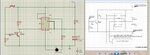
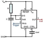
I have seen this circuit which is based on the 555 monostable its purpose is to add a back light to a radio aircraft transmitter screen, I have built the circuit on a breadboard but it does not work so I used Proteus 8 professional to run a simulation of the circuit and although it worked it did not operate as expected, the problem was that when the circuit was started the back-light (an LED) did not light up until the trigger (marked buzzer) contact was made then the LED lit for the set time and continued to light when the contact was made.
In an attempt to get the back-light to operate when first powered on I tried changing some of the components, when I used an animated capacitor which Proteus has in its components to see what was happening when the circuit powered on the circuit worked as it should. I have tried many different types of caps in the simulation but none work as the animated one, unfortunately this cap has no identification it is listed as animated so I have no idea what to use in its place I don't want to build the circuit until I know the required part and it works, I have attached a copy of the original circuit and a screen capture of the working circuit in Proteus any help with this would be gratefully received.
Thanks Les
**broken link removed**