Continue to Site

Welcome to EDAboard.com

Welcome to our site! EDAboard.com is an international Electronics Discussion Forum focused on EDA software, circuits, schematics, books, theory, papers, asic, pld, 8051, DSP, Network, RF, Analog Design, PCB, Service Manuals... and a whole lot more! To participate you need to register. Registration is free. Click here to register now.

Simulation using RF pulsed generator

Status
Not open for further replies.

mohamis288

Full Member level 3
Joined
Mar 1, 2022
Messages
164
Helped
0
Reputation
0
Reaction score
1
Trophy points
18
Activity points
1,235
Hello,
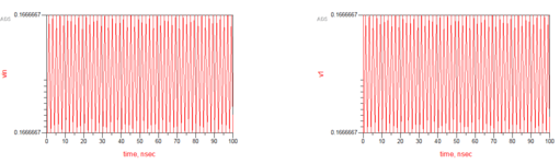
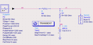
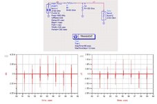
I am simulating a simple test circuit including RFpulsed generator in ADS. but the simulation gave some surprising result. I have attached my test circuit schematic in the attachment. moreover, I have added the simulation plot there. pay attention to the output resistor value of the RFpulsed generator. I have a couple of questions as in the following:
1- the output voltage value of RFpulsed generator probe (vin) is not correct as per its output resistor. what do you think?
2- I have applied a time delay of 50 usec at the beginning and the start time of simulation is 0 sec. the stop time of simulation was set 100 nsec. so, nothing should have been shown in the simulation result. what do you think about?
3- when I want to do transient simulation without the DC supply, while I have the RFpulsed generator, I encounter with an error. what do you think about the reason?

best regards,
thank you
 

Attachments

  • Screenshot (214).png
    Screenshot (214).png
    12.1 KB · Views: 124
  • Screenshot (215).png
    Screenshot (215).png
    58.5 KB · Views: 120

How you have applied 50us time delay since the transient stop time 0.1us ??
Transient stop time must be at least 50.1 us and you should enter
Start Time =50us
Stop Time = 50.1us
Max Step Time=....

Like that.
 

How you have applied 50us time delay since the transient stop time 0.1us ??
Transient stop time must be at least 50.1 us and you should enter
Start Time =50us
Stop Time = 50.1us
Max Step Time=....

Like that.
Hello @BigBoss,
No, please pay attention to the schematic picture and zoom in "PulseRF" property. Delay is defined there. no Delay is applied to the transient simulation.

best regards
 

Hello @BigBoss,
No, please pay attention to the schematic picture and zoom in "PulseRF" property. Delay is defined there. no Delay is applied to the transient simulation.

best regards
That's exactly what I'm saying.
If there is a delay somehow and your aim is to see the result "after this delay" you have to implement this delay in transient analysis too. Its should not stop before delay otherwise you see "zero" due to delay.
Stop time must be at least 50.1us not before than this.
good point!! thank you @BigBoss,
Did you have any opinion about my first and third question?

best regards,
thank you
 

I don't get any error, with or without DC supply.
 

Attachments

  • delay.jpg
    delay.jpg
    151.1 KB · Views: 102

I don't get any error, with or without DC supply.
Hello,
you are using another component instead of "PulseRF" component. moreover, when using "PulseRF" without a DC supply, a message arises and prevent simulation. the message will be uploaded here.
in your simulation, the amplitude are as per expectations. but if zoom in my simulation results, you can see that the amplitude of "vin" is the same as "v1", in contrary to my expectations. can you imply this amount of difference?

best regards
thank you
 

Attachments

  • message.png
    message.png
    13.4 KB · Views: 78

but if zoom in my simulation results, you can see that the amplitude of "vin" is the same as "v1", in contrary to my expectations. can you imply this amount of difference?
We only see equal DC bias voltage, RF magnitude is infinitesimally small. The DC bias suggests that the PulseRF source is AC coupled.

You are complaining that vfone is using a different PulseRF source. Unfortunately you neither tell which ADS version you are using nor from which library PulseRF has been imported.
 

Hello @BigBoss ,
recently I have asked this question and you can find it in the attachment. it may be is not compatible with transient simulation and I should refer to another method to implement pulse generator.

thank you
 

Attachments

  • pulseRF.txt
    124 bytes · Views: 94

This PulseRF source is from the Signal Processing (DSP) components in ADS. It is intended for use within the ADS Ptolemy domain (the clue is the big arrow on the symbol) that can include Circuit Envelope Simulations and certain Transient/Convolution Simulations for modulated signal simulations. However, it will never work for regular circuit level simulations like S-parameter, AC, Harmonic Balance and regular Transient Time Domain (Spice like) simulations.
 
Use the source that I used in my posted simulation and you will sleep well..
 

Status
Not open for further replies.

Similar threads

Part and Inventory Search

Welcome to EDABoard.com

Sponsor

Back
Top