Continue to Site

Welcome to EDAboard.com

Welcome to our site! EDAboard.com is an international Electronics Discussion Forum focused on EDA software, circuits, schematics, books, theory, papers, asic, pld, 8051, DSP, Network, RF, Analog Design, PCB, Service Manuals... and a whole lot more! To participate you need to register. Registration is free. Click here to register now.

[SOLVED] SG3524N 50hz bridge inverter

Status
Not open for further replies.

Iykeeh Ezeonyekwelu

Junior Member level 2
Joined
Jan 15, 2014
Messages
23
Helped
1
Reputation
2
Reaction score
1
Trophy points
3
Activity points
169
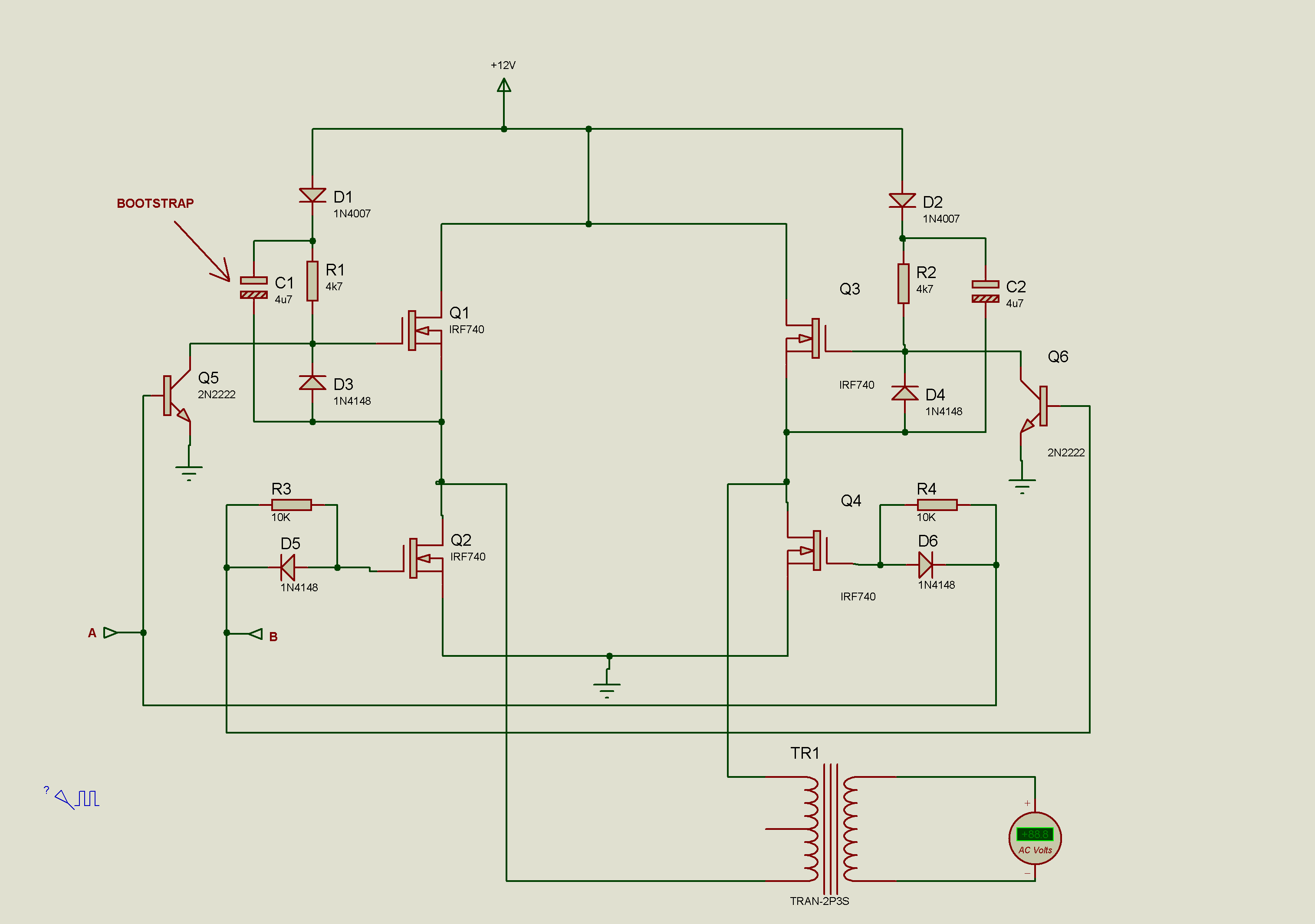
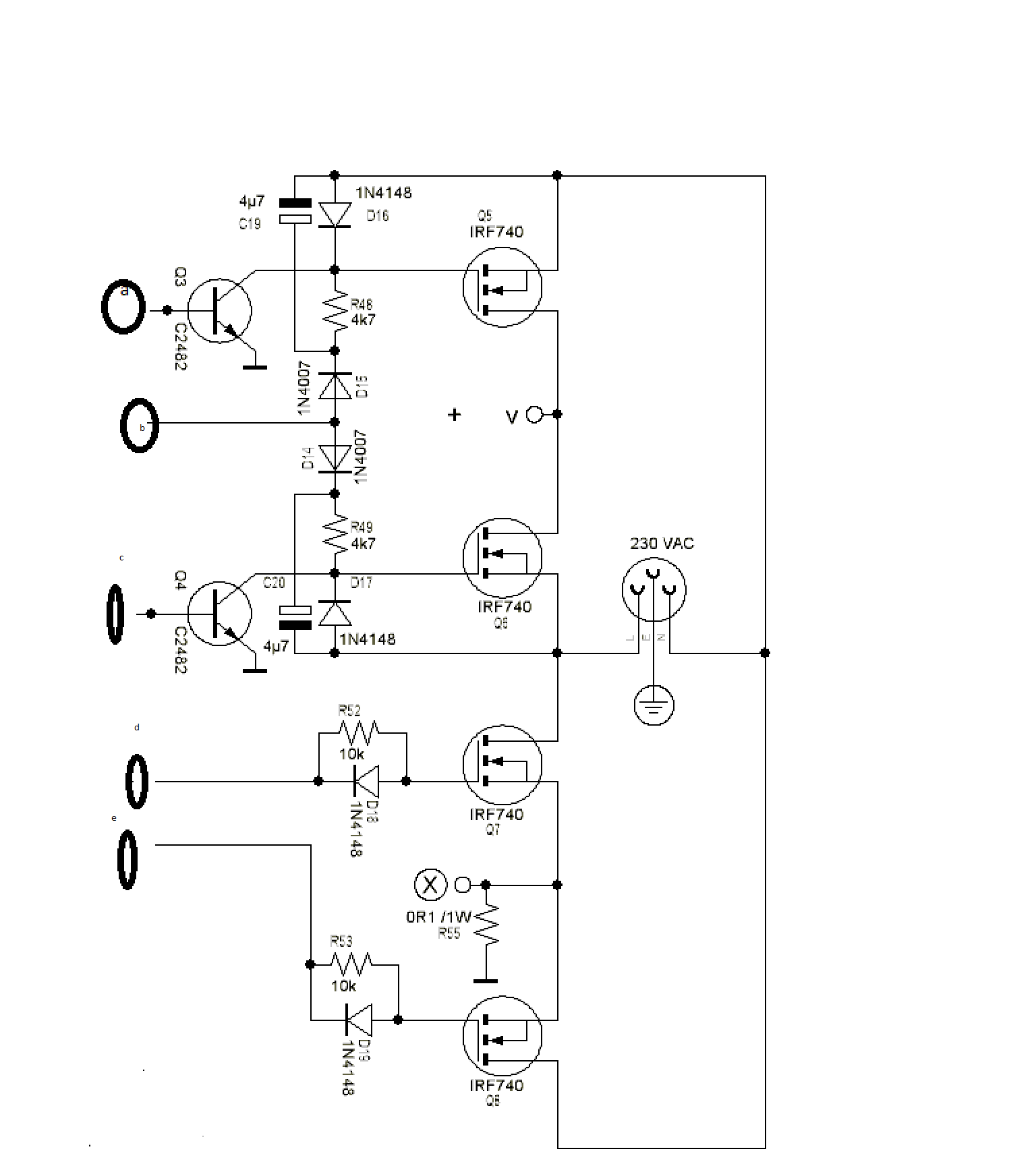
plz I nid help with my 12V bridge inverter ,I have an sg3524n ic which I want to use for my bridge inverter, I designed the ic as a 50hz pwm, I want to feed the signal to a bootstrap that will drive the H-bridge mosfet which will step up my 12v to 220VAC using a transformer but the test circuit I made of the bootstrap for the high side n-channel mosfet using descrete components didn't work when I connect the signal from my sg3524n, I couldn't figure out why. I even placed IN4001 diode with. 1k pulldown resistors at d outputs of d ic bt still didn't work, I don't know why, plz help........here is d oscillator I used, I connected pin 12 and 13 to pin 15 and I only used the part marked "driver stage" ....I also, currently don't have an oscilloscope. Any kind of Help is well appreciated
 

Attachments

  • Bootstrap.png
    Bootstrap.png
    301.6 KB · Views: 209
  • schematicsml.gif
    schematicsml.gif
    50.9 KB · Views: 225
Last edited:

Sorry,
But you do not have bootstrap in your circuit at all.

- - - Updated - - -


Try this.

Cheers.
 

It's not usual bootstrap, but a kind of charge pump that should be also able to drive the gate voltage above the supply voltage. The SG3524 connection isn't shown in the circuit, in any case you should debug the circuit by checking alll waveforms with an oscilloscope, initially with the MOSFETs disconnected.

The gate drive current is low, so will be the switching speed, but it's probably sufficient for a 50 Hz inverter. I see a certain risk that the gate voltage exceeds the MOSFET Vgs rating in negative direction.
 

I have just updated my post and I included the oscillator circuit.
 

Circuit (A) will not work but circuit (B) will work by using the center tap transformer ..
 

it worked as push pull but I want to make it a bridge using small transistors like bc337, bc547, c9014....
 

m 4rm Anambra state but I school in IMT Enugu. Plz hav u tested d circuit n it's confirmed working?
 

hello kabeer, Thanks alot. The circuit is working after some little remod. Without connecting the bootstrap cap and FET I have about 5.8v . My little question is; if I connect it as it should, do u think it will fully switch ON my irf3205 FET because am running it from a 12V? I don't want my FET to light up like Christmas tree.
 
  • Like
Reactions: zkalk

    zkalk

    Points: 2
    Helpful Answer Positive Rating
It will not work without using the bootstrap capacitor your high side mosfet will heat up and burnt so i advise you to use your bootstrap circuit.
 

I will complete it and let u know of the result, I used an opto isolator(pc817) in place of the transistor just for trial but I will use c9014.
 
Last edited:

Status
Not open for further replies.

Similar threads

Part and Inventory Search

Welcome to EDABoard.com

Sponsor

Back
Top