ai.nayem
Newbie
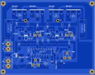
Actually i use a full bridge mosfet circuit after a 320v ferrite core inverter.
This circuit i found from google search.
But the low side mosfet getting extremely hot in few second.
Please help anyone. Please
This circuit i found from google search.
But the low side mosfet getting extremely hot in few second.
Please help anyone. Please