Continue to Site

Welcome to EDAboard.com

Welcome to our site! EDAboard.com is an international Electronics Discussion Forum focused on EDA software, circuits, schematics, books, theory, papers, asic, pld, 8051, DSP, Network, RF, Analog Design, PCB, Service Manuals... and a whole lot more! To participate you need to register. Registration is free. Click here to register now.

Secondary Snubber Calculation for Phase Shifted Full Bridge Inverter

sabu31

Advanced Member level 1
Joined
Jan 28, 2011
Messages
446
Helped
12
Reputation
24
Reaction score
13
Trophy points
1,298
Activity points
5,157
Hi all,

I am testing a phase shifted full bridge inverter. I am facing ringing on secondary side.
Without any snubber, I am seeing the Frequency as around 3.6Mhz and after adding a 10nF capacitor the frequency has reduced. But when I add a series resistor of 15 ohm along with it, there is a huge spike but after that the ringing dies of quickly. I am attaching the waveforms.

without_snuber.png

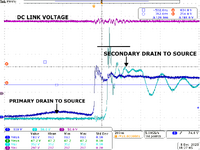
waveforms without using any snubber
Ch 2: Secondary side Device Drain to source voltage


using 10nF.png

Waveforms using 10nF across the drain to source

Ch 2: Secondary side Device Drain to source voltage


After adding a series resistor of 15Ohms, however, the peak again increases. What is the ideal value of resistance (typical range) that should be used for secondary of PSFB.

The device used is SQW61N65EF. What is the capacitance that should be considered for output parasitic capacitance? There are two values given in datasheet

Effective Output Capacitance, Time Related b= 841pF
Effective Output Capacitance, Energy Related a= 213pF

My original schematic is attached. Is there any reference/thumb rule for the calculation of secondary snubber. Also is both R-C snubber and RCD clamp both required in PSFB.
 

Attachments

  • DIPTRACE_PSFB_QUERY.pdf
    43.6 KB · Views: 81
You can experiment with different resistor values in the secondary snubber to find a value that dampens the ringing without causing adverse effects on performance.
 
Without an equivalent circuit with all relevant inductance, it is hard to analyze because appears to be a primary and secondary resonance.
Your secondary 5.6 ohm/5= 1.1 and 470//470pf ~ 1nF with unknown L.

But with 10 nF added the waveform has a Q ~ 10 with 10 cycles when 1st peak decays to 6% which is the rule of how to measure Q on a 2nd order underdamped waveform.

I checked my RLC impedance graph which told me to damp the secondary instead of 1.1 Ohm+ 1nF you need 22 Ohm + 10 nF but this does not filter out the primary resonance. with unknown LC parameters.


If you can create a more realistic RLC model, I find your optimum damping factor. This simulation has a test switch to compare plots with 2 values of R. https://tinyurl.com/ym247o8u

1701891775573.png
 
Last edited:
Without an equivalent circuit with all relevant inductance, it is hard to analyze because appears to be a primary and secondary resonance.
Your secondary 5.6 ohm/5= 1.1 and 470//470pf ~ 1nF with unknown L.

But with 10 nF added the waveform has a Q ~ 10 with 10 cycles when 1st peak decays to 6% which is the rule of how to measure Q on a 2nd order underdamped waveform.

I checked my RLC impedance graph which told me to damp the secondary instead of 1.1 Ohm+ 1nF you need 22 Ohm + 10 nF but this does not filter out the primary resonance. with unknown LC parameters.


If you can create a more realistic RLC model, I find your optimum damping factor. This simulation has a test switch to compare plots with 2 values of R. https://tinyurl.com/ym247o8u

View attachment 186722
Thanks Tony for the reply.

The transformer leakage measured at the secondary side is 980nH (Secondary 1), and 480nH (secondary 2) and that measured at the primary is 6.8uH.
The magnetizing inductance is 1.6mH.

What is the ideal winding configuration for PSFB with centre tap in secondary.

Also is both RCD Clamp and RC snubber both required or any one is enough
 
In continuation with above post, i have calculated RCD clamp value based on the attached pdf.

I am getting the values as per attached pdf. ie the Rclamp=1kOhm, Pclamp=30W and C=56nF.
Is this correct calculation.

Is the value of leakage high for a PSFB Transformer secondary half.

What is the recommended winding arrangement for a PSFB transformer with a centre-tap
 

Attachments

  • RCD_CLAMP.pdf
    256.6 KB · Views: 75
  • RCD CLAMP.pdf
    75.1 KB · Views: 69
My only rule of thumb is to choose a magnetising imepdance XL(f)=10% of rated full load Rin, but the spectrum is much wider on this tri-level pseudo sine, so I don't know how to balance the power loss budget. For damping control I might start with an RLCf impedance choices then verify each component loss effects with sensitivity changes to breakpoints, damping factors or impedance values to loss budget and EMI suppression.
 
Today I tested with RCD Clamp with R=550Ohms, C=0.094uF (Though this was obtained for clamping at 230V, with leakage as 2uH). The clamp structure is as per attached PDF.

The transformer was also changed to ETD49 with primary magnetizing inductance as 3mH. The leakage measured is (Secondary half 1: 464nH and Secondary Half 2: 765nH). The waveforms obtained are attached.

There is only one peak which is very sharp at around 350V rest of the waveform is getting clamped around 250V.


My queries are

a) Is this a single 350V peak (measurement error)? Nevertheless, the snubber resistance started heating (the power of snubber resistance is around 15W, The calculated value is ).

b) Will the Loss in the RCD clamp reduce once Synchronous Rectification is enabled? So should I proceed with testing at higher power levels? Presently its around 450W. I need to test at 1500W.

c) What is the preferred winding arrangement? I am using (Primary Half (15 Turns), Secondary 2 (6 Turns), Primary Half (15 Turns), Secondary 1(6 Turns) with the secondary (S1) closest to the core limb). The primary halves are connected in series.
 

Attachments

  • RCD_CLAMP_RESULTS.png
    RCD_CLAMP_RESULTS.png
    69.9 KB · Views: 47
  • PSFB_CLAMP.pdf
    485.5 KB · Views: 61

LaTeX Commands Quick-Menu:

Part and Inventory Search

Welcome to EDABoard.com

Sponsor

Back
Top