Continue to Site

Welcome to EDAboard.com

Welcome to our site! EDAboard.com is an international Electronics Discussion Forum focused on EDA software, circuits, schematics, books, theory, papers, asic, pld, 8051, DSP, Network, RF, Analog Design, PCB, Service Manuals... and a whole lot more! To participate you need to register. Registration is free. Click here to register now.

SCR Bridge Control - Is my Circuit Correct ?

Status
Not open for further replies.
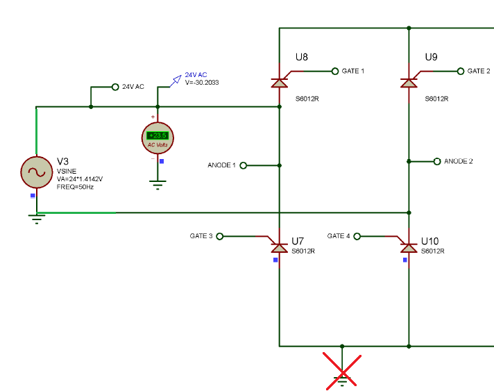
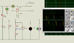
Because in simulation if I use one AC voltage source then it is not simulating. It then works as controlled half wave rectifier. the negative half is not rectified.

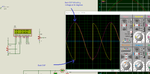
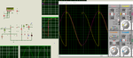
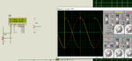
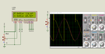
In simulation for RL load the 570V spike is making the SCR to conduct even before the gate is triggered for firing angle greater than 90 degrees. The spike is occuring at exactly 4.9ms from Zero Cross. How to eliminate the spike ? Should I use MOV ?
 

@CataM

I tested it. it works as controlled half-wave rectifier.
 

Can somebody explain why the spike is coming at approximately 90 degrees when firing angle is more than 90 degrees ? spike is coming at 4.9ms after zero cross only for RL load.

AC voltage is 24V 50Hz
L = 50mH
R = 10k

spike is coming at output. Due to the spike the SCRs are conducting even though they are not fired.
 

What I observed is at approx 90 degrees that is 4.9ms after ZC for 50Hz signals there is a large back emf (negative voltage) and this is causing the 570V spike in the Proteus Simulation. How to avoid this spike ? reduce back emf ?

Edit: See pictures

The large back emf suddenly drops to 0V at 90 degrees and this is causing a large spike which is making the scr to conduct always for 90 degrees if firing angle is greater than 90 degrees. If firing angle is greater than 90 degrees then it is neglected and this back emf is triggering the SCRs.

You can see from the pictures that even if firing angle is more than 90 degrees then due to back emf the SCRs are triggering at 90 degrees ot exactly at 4.9ms after ZC.

How to solve this ?
 

Attachments

  • back emf problem for RL load.png
    back emf problem for RL load.png
    100 KB · Views: 78
  • back emf problem for RL load #2.png
    back emf problem for RL load #2.png
    96.7 KB · Views: 84
  • back emf problem for RL load #3.png
    back emf problem for RL load #3.png
    101.7 KB · Views: 70
  • back emf problem for RL load #4.png
    back emf problem for RL load #4.png
    109.6 KB · Views: 73
Last edited:

In real hardware, it's well expectable that MOC3021 without snubber are self-triggering with inductive loads. I don't know enough details about the Proteus model to decide if this might happen in simulation.

It's however easy to determine in simulation where the unwanted triggering happens, e.g. by watching the SCR gate and anode currents.

I'm surprised that your simulation circuit has still two superfluous SCR that can short the supply voltage if triggered inadvertently. I'm not motivated to further guess about circuit problems before they are removed.
 
  • Like
Reactions: Okada

    Okada

    Points: 2
    Helpful Answer Positive Rating
I'm surprised that your simulation circuit has still two superfluous SCR that can short the supply voltage if triggered inadvertently.

You mean I have to use 2x SCRs and 2x Diodes ? But using 4x SCRs is a requirement for the project.

- - - Updated - - -

@FvM

So, I have to design a snubber for MOC3021 circuit ?

Should I design a snubber circuit as shown here for Inductive load ? That is snubber for MOC3021 ?

https://www.avrfreaks.net/sites/default/files/forum_attachments/Design1-1_1.png

- - - Updated - - -

Edit:

Adding a 36V zener across the load as shown in picture solved the problem.
 

Attachments

  • Zener With RL Load.png
    Zener With RL Load.png
    102.8 KB · Views: 77

You mean I have to use 2x SCRs and 2x Diodes ? But using 4x SCRs is a requirement for the project.
I mean that the circuit is presently wired for two SCR and the two lower SCR can short the power supply. Either remove the two SCR or the ground short.
 
  • Like
Reactions: Okada

    Okada

    Points: 2
    Helpful Answer Positive Rating
@FvM

Please don't consider the V3 and V4 connections. Actually the 230V AC is applied to 12-0-12V 500mA transformer primary and 24V AC is given to SCR bridge input. transformer center tap is not used and transformer connections are not connected to ground but the SCR bridge is connected to ground as shown in the previously attached circuits. The PIC power supply bridge ground, ZCD circuits's bridge ground and SCR brisge ground are common. If I disconnect SCR bridge ground shown in the circuit from PIC power supply ground will I get load voltage ? The 24V AC to the SCR circuit is connected to Anode 1 and Anode 2 connections in the circuit.

I have also added a 1k resistor in series with the zener to limit zener current. Is it ok ? zener is 5W type.

Edit:

Please consider only the attached circuit. It is actual hardware circuit. Referring to attached circuit tell me if I remove the SCR Bridge ground then will the circuit work ? Because if I don't connect the SCR bridge to ground then I am not getting output at load in Simulation.

The circuits in other posts are all simulation circuits and the one attached in this post is the real hardware circuit.
 

Attachments

  • SCR Bridge Control.PDF
    40.8 KB · Views: 78
Last edited:

Please don't consider the V3 and V4 connections
Please consider only the attached circuit. It is actual hardware circuit
The circuits in other posts are all simulation circuits and the one attached in this post is the real hardware circuit.
Ask yourself this: - What is the purpose of simulations?
- What is the purpose of modelling a circuit?
- Why are you asking those questions if you already have implemented the circuit in real hardware?
 
  • Like
Reactions: Okada

    Okada

    Points: 2
    Helpful Answer Positive Rating
Real hardware is not yet built. There was a error in PCB layout. So, I designed the new PCB layout according to the circuit in post 109. I will get the hardware on wednesday. Only then I can test with and without zener.

In actual hardware I have used TYN612 and its ratings are 600V, 12A, Igt 15mA

In Simulation I have used other SCR as TYN612 is not available in Proteus and its ratings are 600V, 12A, Igt = 20mA.

I just want to know whether the circuits works if SCR circuit's ground connection is removed. Please refer to circuit in post 109 and answer.
 

A ground connection isn't required in hardware, it's also not permitted because the 230V input is already grounded.

A simulator (SPICE simulator, e.g. Proteus) doesn't like floating circuits, so a ground connection is required. A double ground connection (AC voltage sources and SCRs grounded), as in your previous simulation circuit makes no sense.
 
  • Like
Reactions: Okada

    Okada

    Points: 2
    Helpful Answer Positive Rating
Ok FvM. I will remove the SCR ground connection in the hardware.

it's also not permitted because the 230V input is already grounded.

I am not inputting 230V AC to SCR bridge. I am only inputting 24V AC 50Hz to SCR bridge. No AC sources are connected to PIC ground.


What is the purpose of simulations?

The purpose is to first check if the circuit works. If it works in Simulator then it will be built on hardware and tested. As I already said it is a college project and the student has to show the signals for R and RL load. The RL load should show the negative voltage on scope. I am just helping the student in his project.
 
Last edited:

I will remove the SCR ground connection in the hardware.
In hardware there should be NO ground connection for the SCRs. We are saying that you should do the same in the simulation.
 

@CataM

Here you go CataM. Check the simulation if you have Proteus. if I remove that SCR ground connection then it takes a very long time to simulate. Simulation becomes very very slow. Also if I remove V3 and connect jsut one VSINE source of 24V rms to bridge circuit without grounding the VSINE source then I get distorted output and sine signals. I know it is Proteus problem.

Edit:

It works for R load as needed also if SCR ground connection is removed but not for RL load in Proteus. For RL load I don't get negative voltage across load if SCR ground is removed.


Edit 2:

Yes, It now works without SCR ground for both R and RL loads in Proteus but still have to add the zener.
 

Attachments

  • Proteus Simulation.rar
    107.1 KB · Views: 54
Last edited:

Please check the attached circuit and tell me if this is ok to build on hardware.
 

Attachments

  • SCR Bridge Control.PDF
    41.9 KB · Views: 62

In simulator it meets. Have to test it in hardware. I need a confirmation regarding connections before sending it for PCB fabrication.
 

I am referring this document for RC snubber design. This document is for designing RC snubber for TRIACs.

1. Can I use the same equations in this document for designing RC snubber for SCR ?

I see that dV/dt is mentioned in SCR datasheet but this document mentioned dV/dt(off) and di/dt(off). Where to find these ?

Can somebody show an example of designing RC snubber for TYN612 SCR Bridge circuit ? or guide me about how to do the calculations with an example ?
 

Attachments

  • en.CD00004096.pdf
    587.3 KB · Views: 87

Thank you all for helping me complete the project. Here is the final Proteus Simulation and also the Proteus Simulation results. For SCR Bridge circuit, you can replace the GND connection with Chassis part.

Series resistor for the Zener diode circuit is not shown.
 

Attachments

  • SCR_Bridge_Control - Proteus Simulation And Results.rar
    1.3 MB · Views: 67

Status
Not open for further replies.

Part and Inventory Search

Welcome to EDABoard.com

Sponsor

Back
Top