CataM
Advanced Member level 4
- Joined
- Dec 23, 2015
- Messages
- 1,275
- Helped
- 314
- Reputation
- 628
- Reaction score
- 312
- Trophy points
- 83
- Location
- Madrid, Spain
- Activity points
- 8,409
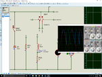
That is why you need a basic Circuit Theory course.I am giving rectified dc to RL load. The voltage doesn't have negative half wave and hence it is not alternating voltage.
I gave you the formula. Can you figure that out with simple derivative of the current with respect to time ?In RL load according to my source at what time the current will be maximum ?
I have never said that. I am saying that who cares if it is -25 or -28. The advantage is that you already know the resistor value for the -28 V. Play around a bit with the resistor if you want -25 V.Why you say I should not take voltage as -25 ?