Mustaine
Member level 1
Hello friends
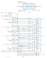
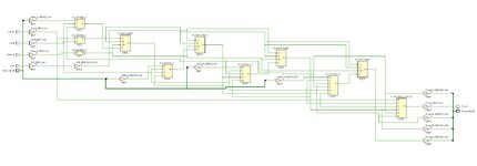
i am currently studying the book digital circuits by morris mano and i am solving a problem which trying to draw the circuit below(Four‐bit binary counter with parallel load) but on vivado i do not know why but the circuit i draw quite different from the book example.
Did i do something wrong?
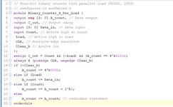
HDL seems okay. Do i interpret the schematics wrongfully i am not sure cause it looks a mess.
Can you give me some advice .
Thanks in advance.
i am currently studying the book digital circuits by morris mano and i am solving a problem which trying to draw the circuit below(Four‐bit binary counter with parallel load) but on vivado i do not know why but the circuit i draw quite different from the book example.
Did i do something wrong?
HDL seems okay. Do i interpret the schematics wrongfully i am not sure cause it looks a mess.
Can you give me some advice .
Thanks in advance.