Continue to Site

Welcome to EDAboard.com

Welcome to our site! EDAboard.com is an international Electronics Discussion Forum focused on EDA software, circuits, schematics, books, theory, papers, asic, pld, 8051, DSP, Network, RF, Analog Design, PCB, Service Manuals... and a whole lot more! To participate you need to register. Registration is free. Click here to register now.

S22 not matching simulation

arwen16

Junior Member level 3
Joined
Sep 3, 2023
Messages
30
Helped
0
Reputation
0
Reaction score
1
Trophy points
8
Activity points
227
Hello,

I had designed an LNA using an HBT from Infineon on ADS and had it fabricated and tested. The S11 measured was a good match with thr simulation results. However, the S22 measured looked like a flipped version of the S22 simulated. I don't know how to debug this issue.
 
I have on my desk an LNA using BFP840 HBT SiGe transistor from Infineon built on a FR4 PCB.
In the range 2.3GHz to 2.5GHz the S21, S11 and S22 are flat at: +20dB, -12dB, and -18dB. The HB simulation shows pretty much the same numbers.
The LNA use only discrete 0402 RLC components.
Important to get good simultaneous S11 and S22 is to use at the LNA input a High-Pass topology matching network, and a Low-Pass topology matching network at the output.
 
I used 4.3 as the permittivity of FR-4.
That's a reasonable average, but you should also run EM with other values in the range 3.9 to 4.7, to see how tolerances affect your design.

When we designed transmission line dividers in the 1-2 GHz range on FR4 long ago, we saw massive differences in results for the exact same layout with FR4 from different manufacturers. This material is poorly defined for RF properties, permittivity depends on the mixture of fiber and resin, and fiber pattern/fiber density can be rather different.
You might consider affordable well defined (!) RF substrates like Rogers RO4003 which can be processed in normal PCB process (no special teflon process required).
 
I used 4.3 as the permittivity of FR-4. I understand that the substrate is not ideal. However, since the LNA design is a part of research work, we wanted to first test the proof of concept of a cheap substrate and then move on to better options like Rogers, Taconic, etc.
--- Updated ---


I have covered the part relevant to my research. In the first picture, I have used this to generate my EM results and then done the EM co-simulation later. I did not incorporate the vias at this point. I simulated from 0 to 12 GHz and used 60 cells/wavelength in the EM setup. The second picture is what I gave for fabrication with the vias. The bias network worked just fine. I got the exact collector current. The S11 measured also agreed well with the measurement results.
If you omitted the VIAs, the result will certainly be different. That explains why the measured and simulated results are very different. VIAs MUST be taken into account in EM simulations. At least, closer VIAs to Microstrip lines must be placed along lines. You show us completely two different layouts in term of EM principles. They are not absolutely same.
Also, FR-4 is not a appropriate substrate beyond 2-3GHz because the permittivity and Loss Tangent of FR-4 exhibit very broad variation over frequency. A more serious and professional result can be obtained by using more stable substrate over temperature, frequency and manufacturing process.
RF Design is not easy and cheap.
Could you please explain this statement " At least, closer VIAS to Microstrip lines must be placed along lines."? Also, I was told to place a lot of vias to mimic ideal ground, so that we wouldn't need to incorporate each individual via in the EM simulation. I understand that there would be some discrepancy between measured and simulated data. I thought since S11 came out well, there should not have been an issue with S22.
 
I have used the BFP740FESD HBT from Infineon. I used an FR-4 substrate of 1.6mm thickness.
.
When I was a Bachelor of Science, I bought FR4 in Turkey and I measured its permittivity (DK) and loss tangent according to the Nicolson-Ross-Weir method. Then I designed antennas in CST. I produced it and I measured them using VNA. After, The measurement result and simulation were perfectly matched.

When I Master of Science, I also used BFP740. But my purpose was to design Microwave oscillators. Eventually, my result and simulation approached each other. I used the AWR student version and the AWR online library.

I suggest you first measure your FR4 permittivity and loss tangent. High possibility your FR4's DK and loss tangent are different. You should simulate and produce again according to your measured DK.

Maybe AWR AXIEM will help you further.

Your emitter's traces are so big. Your ground polygons are bad. I think your emitter's ground planes should be smaller. :)

.
 
Last edited:
I did not incorporate the vias at this point.
1) What vias and where? Using circuit simulation vias instead of including them in simulation can have a large effect, especially for your thick substrate.

2) The pads seen at the bottom side seem to be supply pads. If you connect them to ideal sources in simulation, these sources are shorting residual RF at that location, but in real world you connect some wires there -> not an RF short. Check if you need additional RF blocking on the supply lines. One easy test is to insert some large series L (100nH or so) there in simulation, and see if that makes a difference.

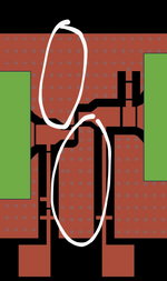
3) For SMD devices you have placed vias on the edges of the wide lines. But real devices are much smaller in width than port you simulated, creating a discontinuity (mostly series L) at these junctions. For more accurate results, the port width can be defined explicitely, instead of using the entire polygon width. https://muehlhaus.com/support/ads-application-notes/edge-area-pins

portwidth2.png

--- Updated ---

I suggest you first measure your FR4 permittivity and loss tangent. High possibility your FR4's DK and loss tangent are different. You should simulate and produce again according to your measured DK.
Yes, this works if you are always using the exact same FR4 from one supplier.

As written above, we had bad experience with FR4 variation. During prototyping, we had used measured data (er=4.7 tand=0.027) and always the exact same FR4 from a single supplier (Bungard). That worked during our prototyping, but was really different from FR4 used by the PCB manufacturer (e.g. FR4 from Isola). The entire production batch was off because their FR4 permittivity was too different from our prototyping FR4.
--- Updated ---

I thought since S11 came out well, there should not have been an issue with S22.
The transistor input and output impedance are rather different, so some effects/parasitics might have different impact.
In addition to the modelling issues mentioned above, you didn't mention how you included the SMD devices. You should use manufacturer data (including parasitics) instead of ideal RLC.
 
Last edited:
1) What vias and where? Using circuit simulation vias instead of including them in simulation can have a large effect, especially for your thick substrate.

2) The pads seen at the bottom side seem to be supply pads. If you connect them to ideal sources in simulation, these sources are shorting residual RF at that location, but in real world you connect some wires there -> not an RF short. Check if you need additional RF blocking on the supply lines. One easy test is to insert some large series L (100nH or so) there in simulation, and see if that makes a difference.

3) For SMD devices you have placed vias on the edges of the wide lines. But real devices are much smaller in width than port you simulated, creating a discontinuity (mostly series L) at these junctions. For more accurate results, the port width can be defined explicitely, instead of using the entire polygon width. https://muehlhaus.com/support/ads-application-notes/edge-area-pins

View attachment 184823
--- Updated ---


Yes, this works if you are always using the exact same FR4 from one supplier.

As written above, we had bad experience with FR4 variation. During prototyping, we had used measured data (er=4.7 tand=0.027) and always the exact same FR4 from a single supplier (Bungard). That worked during our prototyping, but was really different from FR4 used by the PCB manufacturer (e.g. FR4 from Isola). The entire production batch was off because their FR4 permittivity was too different from our prototyping FR4.
Thank you so much. I will definitely look into the pin (port) width as you mentioned.
As for the ground, I used ideal ground in my circuit simulation and did not include vias in my EM simulation. I was told if you place a lot of vias then it mimics an ideal ground and hence you would not need to simulate each via. Is the proximity of my vias to the TLs affecting the response too?
--- Updated ---

1) What vias and where? Using circuit simulation vias instead of including them in simulation can have a large effect, especially for your thick substrate.

2) The pads seen at the bottom side seem to be supply pads. If you connect them to ideal sources in simulation, these sources are shorting residual RF at that location, but in real world you connect some wires there -> not an RF short. Check if you need additional RF blocking on the supply lines. One easy test is to insert some large series L (100nH or so) there in simulation, and see if that makes a difference.

3) For SMD devices you have placed vias on the edges of the wide lines. But real devices are much smaller in width than port you simulated, creating a discontinuity (mostly series L) at these junctions. For more accurate results, the port width can be defined explicitely, instead of using the entire polygon width. https://muehlhaus.com/support/ads-application-notes/edge-area-pins

View attachment 184823
--- Updated ---


Yes, this works if you are always using the exact same FR4 from one supplier.

As written above, we had bad experience with FR4 variation. During prototyping, we had used measured data (er=4.7 tand=0.027) and always the exact same FR4 from a single supplier (Bungard). That worked during our prototyping, but was really different from FR4 used by the PCB manufacturer (e.g. FR4 from Isola). The entire production batch was off because their FR4 permittivity was too different from our prototyping FR4.
--- Updated ---


The transistor input and output impedance are rather different, so some effects/parasitics might have different impact.
In addition to the modelling issues mentioned above, you didn't mention how you included the SMD devices. You should use manufacturer data (including parasitics) instead of ideal RLC.

I used SMD models available for the RLC components. Also, I ensured that components have really high SRF (>40GHz) to have minimum impact on my circuit.
 
As for the ground, I used ideal ground in my circuit simulation and did not include vias in my EM simulation. I was told if you place a lot of vias then it mimics an ideal ground and hence you would not need to simulate each via. Is the proximity of my vias to the TLs affecting the response too?
I would not be worried about that proximity.

But you should definitely include the actual vias at the transistor in EM, because you have a really thick substrate, and that is a very sensitive location! Placing many vias might sound great, but if we look at current density in simulation we see that RF current prefers the shortest path, and adding more vias has less effect than expected.

Also note the topic of SMD models that I added above. You should not trust ideal RLC at these frequencies, manufacturers like Murata have ADS designkits with accurate SMD data.

I have used the design kits of Murata only in my simulation. I apologise for using the term SMD model. I meant design kit.

I have marked the vias that will be connected to the emitter in the image attached. Just so that I am clear, do you mean these vias should be added in my EM simulation?
 

Attachments

  • Final~3.png
    Final~3.png
    310.3 KB · Views: 49
I have marked the vias that will be connected to the emitter in the image attached. Just so that I am clear, do you mean these vias should be added in my EM simulation?
Yes, absolutely! This is very critical!

Also include the side grounds in EM, because this is rather close and will provide additional ground (=capacitive load) to your wide lines.

And don't forget my comment on your supply lines/pads, this looks like a mistake also.
 
Yes, absolutely! This is very critical!

Also include the side grounds in EM, because this is rather close and will provide additional ground (=capacitive load) to your wide lines.

And don't forget my comment on your supply lines/pads, this looks like a mistake also.

I don't understand the term "side grounds"? I would be really grateful if you could mark the grounds in the image that I should consider.

Also, I shall surely take care about the supply line.
 
I don't understand the term "side grounds"? I would be really grateful if you could mark the grounds in the image that I should consider.
I mean all the side ground on top layer. You have hidden much of your design, but it seems that you have flooded the top layer with ground at ~1mm distance from the microstrip lines. Your bottom ground is at 1.5mm distance, and compared to that the side grounds are not far away! That additional ground on top layer, at that distance, will increase the capacitive load of your lines -> lower line impedance Zline=sqrt(L'/C').

You should really include that top layer ground, including vias, in EM simulation!

sidegnd.png
 
I mean all the side ground on top layer. You have hidden much of your design, but it seems that you have flooded the top layer with ground at ~1mm distance from the microstrip lines. Your bottom ground is at 1.5mm distance, and compared to that the side grounds are not far away! That additional ground on top layer, at that distance, will increase the capacitive load of your lines -> lower line impedance Zline=sqrt(L'/C').

You should really include that top layer ground, including vias, in EM simulation!

View attachment 184826

Ok, I understand now. Thank you so much. I will incorporate everything mentioned in my EM simulation.
 
One m
I have on my desk an LNA using BFP840 HBT SiGe transistor from Infineon built on a FR4 PCB.
In the range 2.3GHz to 2.5GHz the S21, S11 and S22 are flat at: +20dB, -12dB, and -18dB. The HB simulation shows pretty much the same numbers.
The LNA use only discrete 0402 RLC components.
Important to get good simultaneous S11 and S22 is to use at the LNA input a High-Pass topology matching network, and a Low-Pass topology matching network at the output.
You have mentioned that these measured quantities above.
They are pretty good numbers (S21=20dB, S11=-12dB, S22=-18dB respectively)
OR are they simulated numbers ??
One more question ; Did you do "Noise Matching" or " Conjugate Matching" ??
'cos these matching might exhibit quite different results.
For LNA, Noise Matching has the priority, for Gain Block, Conjugate Matching takes the priority over than.
 
Most of the 2.4GHz LNA applications from Infineon use FR4:

I never had problems using FR4 designing LNAs for 2.4GHz.
But I see many antenna designs on FR4, and there could be a problem if you look for high repeatability.
Also designing 2.4GHz VCOs on FR4 could be problematic, but again, not for LNAs.

On my LNA, measured and simulated numbers are almost the same, for the frequency range that I mentioned.
Always you have to do noise matching if is about a Low Noise Amplifier, otherwise will be a simple Amplifier.
Again, very important for a single device LNA is the inp/out matching network topology that I mentioned above.
 
I never had problems using FR4 designing LNAs for 2.4GHz.
You wrote above that your LNA uses discrete components, just like the Infineon appnote. Substrate loss and permittivity is less critical then, if the lines are just interconnect.

arwen16 wrote that his "matching network was designed using microstrip line", so his undisclosed secret circuit part might be more sensitive to substrate properties.
 
Of course this is the difference. When using FR4 I recommend using LC discrete components up to their frequency limits. At 2.4GHz still can get reasonable LC values.
Microstrip and printed components on FR4 are affected by the substrate even at lower frequencies than 2.4GHz.
 
I mean all the side ground on top layer. You have hidden much of your design, but it seems that you have flooded the top layer with ground at ~1mm distance from the microstrip lines. Your bottom ground is at 1.5mm distance, and compared to that the side grounds are not far away! That additional ground on top layer, at that distance, will increase the capacitive load of your lines -> lower line impedance Zline=sqrt(L'/C').

You should really include that top layer ground, including vias, in EM simulation!

View attachment 184826
I did take the vias around the transistor into consideration and it had an impact on the EM results. Without matching (just the transistor, bias network, and stability network), using an ideal ground, I could achieve up to 14 dB gain. Once I added the vias, however, the gain dropped to 11 dB. How can I improve the grounding near the transistor?
 
You already have several closely spaced vias, so there is little room for improvement without going to a thinner substrate.
I understand. At this moment, I am afraid I do not have the option to change my substrate. So, I tried simulating my final design keeping the vias in the design. I set up the adaptive frequency from DC to 11 GHz (upto third harmonic) with 50 points. I set the mesh frequency to 6 GHz and the number of cells/wavelength= 80. The EM simulation is taking a really long time (more than a day). I want to understand if I am doing this right. I wish to reduce the simulation time.
 

LaTeX Commands Quick-Menu:

Similar threads

Part and Inventory Search

Welcome to EDABoard.com

Sponsor

Back
Top