ronic
Newbie
Hello,
I use the Cadence PowerSI Model Extraction tool to get the S-parameters of a small and simple PCB.
this PCB is roughly a simple wire connecting 1 input connector to 1 output connector for 6 channels (then 12 connectors in total).
this PCB is about 15cm x 10cm large.
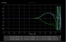
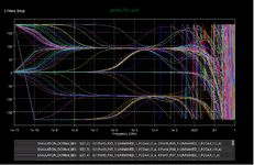
I'm surprised that the Model Extraction tool gives me different S-parameter phases (between -180° and + 180° depending on simulation options) for very low frequencies, let's say below 1Hz.
for me, at very low frequencies, the insulation is almost a leakage (big) resistor and the conductors are not inductive anymore, and then they are (small) resistors too.
in addition, the delay due to the size of the board is at the nanosecond scale and should not bring any phase difference for 1Hz waves.
then, all the S-parameters in transmission should have a phase equal to zero at low frequencies.
do you think this conclusion is correct?
do you have any idea why this kind of software, dedicated to S-parameter extraction, can make such an error and how to correct it?
thanks for your thoughts and help
best regards
ronic
I use the Cadence PowerSI Model Extraction tool to get the S-parameters of a small and simple PCB.
this PCB is roughly a simple wire connecting 1 input connector to 1 output connector for 6 channels (then 12 connectors in total).
this PCB is about 15cm x 10cm large.
I'm surprised that the Model Extraction tool gives me different S-parameter phases (between -180° and + 180° depending on simulation options) for very low frequencies, let's say below 1Hz.
for me, at very low frequencies, the insulation is almost a leakage (big) resistor and the conductors are not inductive anymore, and then they are (small) resistors too.
in addition, the delay due to the size of the board is at the nanosecond scale and should not bring any phase difference for 1Hz waves.
then, all the S-parameters in transmission should have a phase equal to zero at low frequencies.
do you think this conclusion is correct?
do you have any idea why this kind of software, dedicated to S-parameter extraction, can make such an error and how to correct it?
thanks for your thoughts and help
best regards
ronic
")

