Continue to Site

Welcome to EDAboard.com

Welcome to our site! EDAboard.com is an international Electronics Discussion Forum focused on EDA software, circuits, schematics, books, theory, papers, asic, pld, 8051, DSP, Network, RF, Analog Design, PCB, Service Manuals... and a whole lot more! To participate you need to register. Registration is free. Click here to register now.

regulator capacitor logic

yefj

Advanced Member level 4
Joined
Sep 12, 2019
Messages
1,195
Helped
1
Reputation
2
Reaction score
3
Trophy points
38
Activity points
7,217
Hello, I have a basic regulator shown below. I use LT1084 instead of LD1084 and As you can see the simulator works great without capacitors.
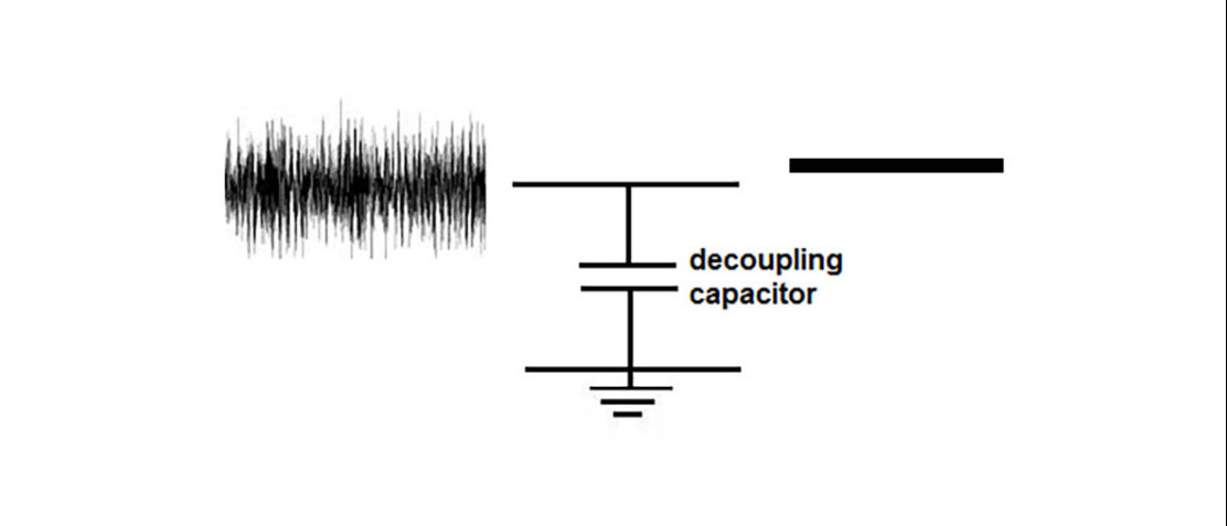
I understand that capacitors are used to filter out the noise from power supply.

I have a circuit which uses a lot of capacitors both near input and output as shown in the photo in the end.
1.The network starts with polarised capacitor as shown in the blue arrow, why polarized?
2.why we have two networks both input and ouput?
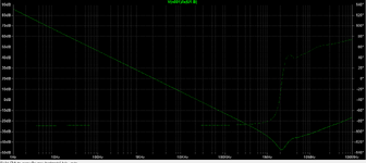
3.I know how to simulation AC filter responce. how can i know based on the networks to what purpose they where planned for?
Thanks.


LD1084:

LT1084:

1692604741065.png


1692606520280.png
 
Look at page 10 for output C recommendations for stability reasons and transient
response considerations.


C3 is typically ceramic to handle high freq noise due to its better ESR at high freq.

OSCON is polymer tantalum :

1692616972687.png


The input C of 1 uF tant is not a speced minimum, but shows up as a configuration in the
transient load and line response curves. So I would advise keep it. A tant for ESR reasons recommended per these graphs.
Regards, Dana.
 
Last edited:
Both devices are classical linear regulators, not specifically designed for ceramic-capacitor-stable operation. LD1084 datasheet has stability curves marking low ESR output capacitor as potential stability issue. LT1084 datasheet doesn't address stability with low ESR output capacitor but suggests tantalum and aluminium electrolyt capacitors.

Capacitor values in post #1 are apparently not based on any datasheet or application note.
 
Might be prudent to post on Analog Devices help forum if there are any
constraints on using high C valued ceramics on LT1084 output. Or contact
their FAE.

Note schematic in post #1 calls out 1 nF cap on output, and one assumes
that would have been a ceramic recommendation for HF noise. So most LDOs
would probably assume that would not be a minimum ESR problem as many
LDOs have on their output caps. But prudence demands I think contacting the
originators / vendors of the part for final say.


Regards, Dana.
 
Hello Dana ,how do we know from data sheet that 10u 1u 1n in parralel?
Also i tried to see the filer response as shown bellow ,
but i get only Vin=Vout.
Where di i go wrong simulation the decoupling system?
Thanks.

1692725944276.png
 
The low-ESR problem is the old classic "op amp driving
capacitive load problem" and seems the solution is also
the same - resistive "degeneration" of the bulk C outside
the feeback loop (here, that's built into the capacitor body).
 
Hi,

as @KlausST mentioned, to see a (lowpass) filter response a "length" resistor is missing. Further, as already mentioned, without the ESR and ESL, you will not see a realistic behaviour, compare the plot below with the Z vs. f graph shown in reply #2.

1692732812332.png


BR
 
Any component in parallel with an ideal V source has no effect on node V,
just the current thru source.

Here is a way over simplified sim of bypassing. A real sim would have RLC
spice values for each. Here its just C value in an ideal cap.

There are two curves, one with bulk 10 u cap at 0 uF and then at 10 uF. You can see the
effects on the noise. I used 10 ohms for source Z and 200 mV RMS of noise.

1692733346397.png


If a spectral sim was also done you would see effects on that as well.

Here is spectral case again where C1 is 10 uF and 0 uF

1692733779297.png


Again this is a way over simplified sim, but you get the point. If real L and ESR values were in model
of each cap youy would see the 1 uF and then the 1 nF exhibit more higher freq efefcts as their
ESR "typically" would be progressively lower and at higher freq.

1692734102223.png


Regards, Dana.
 
Last edited:
Hello Dana, i have the following cl21a106koqnnne capacitor which i want to excract its ESR and make an equivalent model.
I could not find any spice model for this component.
How do i extract the ESR ESL from the data sheet?
Thank.


1692793131577.png

--- Updated ---

UPDATE:
Hello Dana, i got the ESR plot for one on my capacitors from the link bellow.
How do i know how to calculate the ESR ESL values from this plot?
Thanks.

1692795769789.png

--- Updated ---

UPDATE:
Hello Dana, i got the ESR plot for one on my capacitors from the link bellow.
How do i know how to calculate the ESR ESL values from this plot?
Thanks.

1692795769789.png
 
Last edited:
I think you can consider the most basic model of a C as a series R L C model.

1692799871485.png


You can ignore the Rp.

Thats not a precise model, because of technology used in C and its packaging,
but can suffice for gross examinations of circuits.

So it has a series resonance, and that means Xl = Xc, and due to phase difefrence at
resonance the sum = 0. So just the ESR is left, which is bottom point in graph.

Next compute C from Xc = 1 / [ 2 * pi * f * C ], solve for C in the graph say midway
down the C slope region.

Do the same for Xl = 2 * pi * f * L, solve for L in the graph say midway up the L slope region.


Regards, Dana.
 
  • Like
Reactions: yefj

    yefj

    Points: 2
    Helpful Answer Positive Rating
Hello Stenzer,I have down loaded the MOD and symbol files from the link you posted.
From these files i made a simulation as shown below.
We want a low impedance at some region
I read that these networks are fro two purposes :
1. to avoid DC supply fluctuations.
2. to filter out noise

given my LD1084V component how do i know at what region i should aim my decoupling network to at low impedance?

Thanks.
1692850398880.png

1692850548877.png
 

Attachments

  • 1692850361245.png
    1692850361245.png
    49.6 KB · Views: 65

    FvM

    Points: 2
    Helpful Answer Positive Rating
Stenzers post on Kemet tool one of the best tools I have seen on decades old
incomplete seat of the pants design approaches for bypassing. As always engineering
excellence continues to evolve.

1. to avoid DC supply fluctuations.
2. to filter out noise

You have not specified any goals in this area, your actual requirements. You need to
clarify the spectrum of interest that you need to focus on and the actual values of
ripple and noise you are willing toi live with. There are designs that add ferrites to
create LC filters as noise reduction in higher frequency applications. One can even
add bulk L to drop ripple, although thats rarely needed these days. Many variants
and considerations.


On ripple, many circuits these days use OpAmps and regulators which have high PSRR
specs, typically. Keep in mind there are usually curves in datasheets that show that is also
freq dependent.


So if your designs focus on audio type frequencies, than bulk C's are what make the
difference. If the focus is on 1 Mhz like suppression than ceramics rule, if 100 Mhz than
ferrites an additional consideration, what are your noise and ripple requirements ?

General ref material :


Regards, Dana.
 
Last edited:
Any component in parallel with an ideal V source has no effect on node V,
just the current thru source.

Here is a way over simplified sim of bypassing. A real sim would have RLC
spice values for each. Here its just C value in an ideal cap.

There are two curves, one with bulk 10 u cap at 0 uF and then at 10 uF. You can see the
effects on the noise. I used 10 ohms for source Z and 200 mV RMS of noise.

View attachment 184581

If a spectral sim was also done you would see effects on that as well.

Here is spectral case again where C1 is 10 uF and 0 uF

View attachment 184582

Again this is a way over simplified sim, but you get the point. If real L and ESR values were in model
of each cap youy would see the 1 uF and then the 1 nF exhibit more higher freq efefcts as their
ESR "typically" would be progressively lower and at higher freq.

View attachment 184583


Regards, Dana.


Hello Dana,I want to recreate the noise simulation you did with the capacitors and without them.
Could you please help me with the following points:

1.Why do we put ceramic 0.1uF capacitors both on input and output of the device?
why not just to put on the output?
2.What noise do you recommend to input the system?
3.what tool did you use to simulate?
Is it possible to do also in LTSPICE?
Thanks.
 
1.Why do we put ceramic 0.1uF capacitors both on input and output of the device?
why not just to put on the output?
2.What noise do you recommend to input the system?
3.what tool did you use to simulate?
Is it possible to do also in LTSPICE?

1) Input C is to keep noise from being injected into the input of regulator. Keep
in mind its ripple/noise rejection is a f() of frequency, and drops :

1693044142044.png


Output C to suppress load generated noise.

2) I just used a broadband white noise source in sim.

3) Simetrix is tool I used.

4) Yes.

Note here is recommended configuration for 3 Terminal regulators including
protection diodes. This is for LM317 but general principles apply.

1693044820006.png


Note on most LDO regulators there is a minimum ESR requirement imposed on
output bulk cap to insure stability. Consult data sheet for that information.

https://www.st.com/resource/en/datasheet/ld1084.pdf page 11


Regards, Dana.
 
Last edited:
Hello Dana,I am building a voltage regulator for 10GHZ system.
Shown bellow 10uF and 1uF connected in parralel i have my low impedance profile at 10Mhz.
I fyou could please help me with follwong points.
1.Why low impedance profile network connected in series to the regulator will make our noise not to go inside the regulator?
2.should i pud ths network in parralel?
3.The low impedance bellow is at 10MHZ its a 10uF and 1uF what capacitors shown i use to get my low impedance network at the 10GHZ mark so my system will not get noise at 10GHZ from the regulator?


1693141258025.png
 
Hi,

a power supply for a 10GHz circuit ...
you need to use proper bypassing capacitors at the load side. Additional series L or series R will decouple the 10GHz from the regulator.
Thus the regulator basically just sees DC load.

This LC or RC filter may have a cutoff frequency of a couple of kHz or even lower.
(By using ferrite beads, coreless inductors, several capacitors of different values in parallel)

****
Mind: while a capacitor acts like a charge reservoir it´s voltage will still change with (AC) load current.
So now you need a series impedance to filter this remainning AC voltage.

10GHz sine with an RMS current of 100mA at a 1nF ideal capacitor will cause an AC voltage of 33.4mV RMS
(334mOhms capacitor impedance)
Now imagine you have a (non realistic ) power source with
* 1mOhms @ 10GHz (non realistic ), then the power supply sees almost the full 100 mA RMS
* added a 1 Ohms series resistor --> something below 30mA RMS
* added a 10 Ohms series resistor --> something about 3.3mA RMS
* added a 100 Ohms impedance (ferrite bead) --> about 334uA RMS

********
Please feel free to use a circuit simulation software to check voltages and currents on your own.

Klaus
 

LaTeX Commands Quick-Menu:

Similar threads

Part and Inventory Search

Welcome to EDABoard.com

Sponsor

Back
Top