nileshthakare2
Member level 1
Hi
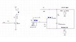
i have some problem in triac circuit.My triac is continuously in on condition.if anyone knowns about the problem with my circuit please help me.i have attach link of my schematic design.(https://obrazki.elektroda.pl/52_1312605496.jpg)
thanks
nilesh)
i have some problem in triac circuit.My triac is continuously in on condition.if anyone knowns about the problem with my circuit please help me.i have attach link of my schematic design.(https://obrazki.elektroda.pl/52_1312605496.jpg)
thanks
nilesh)