omarelmorsy
Junior Member level 1
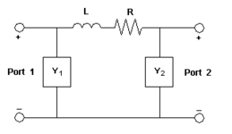
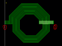
When I create a series (floating) 2-port inductor in sonnet I know it is equivalent to a pi model where we have a series R and series L and shunt components at the 2 ports.
after eming the inductor using sonnet, I knew that inductance 2 represents the series inductance and same for resistance 2 also represents series resistance.
1) I wanted to know what is the quality factor of that (series/floating) inductor, as Q represents quality factor if port 2 is grounded and Q3 represents quality factor for differential inductor, but how to calculate quality factor for the floating inductor ?
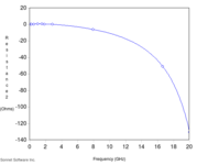
2) After I emmed an inductor I found that resistance 2 has negative value at some frequencies is that even possible or did I do something wrong ?
after eming the inductor using sonnet, I knew that inductance 2 represents the series inductance and same for resistance 2 also represents series resistance.
1) I wanted to know what is the quality factor of that (series/floating) inductor, as Q represents quality factor if port 2 is grounded and Q3 represents quality factor for differential inductor, but how to calculate quality factor for the floating inductor ?
2) After I emmed an inductor I found that resistance 2 has negative value at some frequencies is that even possible or did I do something wrong ?