Continue to Site

Welcome to EDAboard.com

Welcome to our site! EDAboard.com is an international Electronics Discussion Forum focused on EDA software, circuits, schematics, books, theory, papers, asic, pld, 8051, DSP, Network, RF, Analog Design, PCB, Service Manuals... and a whole lot more! To participate you need to register. Registration is free. Click here to register now.

[SOLVED] PT100 Interface using Controller

Status
Not open for further replies.

gauravkothari23

Advanced Member level 2
Joined
Mar 21, 2015
Messages
640
Helped
5
Reputation
10
Reaction score
4
Trophy points
1,298
Activity points
6,922
Hi All..
I am trying to interface PT100 2 Pin with Controller. I am using NUVOTON NUC029LAN Controller.
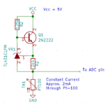
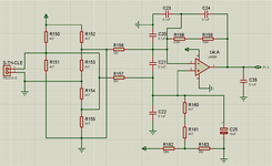
Circuit diagram has also being attached for PT100 Interface. I am using Internal ADC of controller.
My Question is how should i calibrate PT100 with Controller. currently i am using POT to calibrate it with multimeter connected. when i connect the POT and measure the resistance at multimeter of 117.77 Ohms which is 45 Degree C, and connect it to the circuit, the resistance Increases to 175 Ohms and voltage at ADC PIN is Approx 4.10V, as soon as i disconnect the Multimeter, the voltage drops to 1.42V. so which is the correct value, and how should i interface it.
I am new in interfacing PT100 with controller.
 

Attachments

  • PT100.png
    PT100.png
    81.5 KB · Views: 1,049

Hi,

The 2mA have nothing to do with ADC.
And an ADC does not "give", it "reads" or better say it converts analog input voltage in digital values.

And at this point .... the ADC was/is not yet of interest.

In my above description I went step by step from
* requirement
* to sensor
* error / accuracy calculations
* signal conditioning calculations
next steps are:
* gain / offset setting calculations (to adjust 188mV ... 224mV to the ADC input range)
* bandwidth limiting / anti alias filtering
* ADC
* software considerations (digital filters, offset calibration, gain calibration, maybe linearisation)

Also to consider:
* ESD protection
* EMI/EMC considerations

Klaus
Thanks, got your point,
think have clear lot of doubts.
needs to calibrate for lot of default values, and then store it in EEPROM.
surely now will try from my side.

I have a question regarding the same.
how can i multiply float values,
for Eg:
Float X.
X = 2*-2;

so the answer has to be 0, but i am getting -4.


Hi,

some languages "force" a float by using a decimal point.
For example: X = 2.0 x -2.0.
The result still is "-4" and should be "-4".
0 is wrong.

needs to calibrate for lot of default values, and then store it in EEPROM.
No. At least I don´t expect it.
This is why I´d use a constant current source, so the result should be precise and linear.

If you don´t use a current source you get non linear result. Then ... you have to use a table to correct the values. I´d avoid this situation.

Klaus
 

For Pt-100 constant current source is a must (unless you are German, an have other ideas :D )

As of weird ideas, here is a partial schematic for measuring temperature in an old Heraeus oven:
 

Attachments

  • Oven-partial.pdf
    22.1 KB · Views: 119
Hi,

I am German (good or bad - I had no chance to choose it). And I agree that constant current method should be used for a precise (linear) measurement.

Analyzing the given circuit:
The PT100 resistance changes about 0.40 Ohms per 1°C. With a 100k series resistance the current changes just 4ppm/K.
This is rather constant. So this is not the true precision problem of the circuit.
The caused linearity error is about 0.1°C at 100°C sensor temperature difference.
Supply voltage errors will be worse.
The temperature drift of the used TL062 is specified with typ. 10uV/°C this equals to 0.5°C...This means every 1°C of OPAMP temperature drift is likely to cause 0.5°C of comparator (sensor) threshold drift.
So if one just changes the circuit to use a (perfect) constant current source, it won´t improve overall performance.
--> It´s a simple and rather non precise circuit.

Klaus
You are missing point about circuit that I attached.
On the input is NiCr-Ni thermocouple :) (no need for CCSource) and instead connecting it, after the amplifier to ADC, it is connected to comparator whose second input is driven by DAC ZN428 and output connected to uC (via PIO chip :D ) instead using ADC, for example ZN427, which is from same era.
 

Hi,

Is getting off topic..

Indeed I don´t think it´s a true temperature measurement, instead an ON/OFF heater control.. or something similar.
The DAC is used to give the temperature setpoint. Don´t you think so?

Klaus
 

Hi,

Is getting off topic..

Indeed I don´t think it´s a true temperature measurement, instead an ON/OFF heater control.. or something similar.
The DAC is used to give the temperature setpoint. Don´t you think so?

Klaus
i am trying, but dont know, where to start,
how can i measure the values, with only voltage which i have on ADC.
from where can i measure the mV.
 

Hello,

My quoted text #30 refers to ZASto´s circuit of #25.. not to your project.

****
Go back and read my posts at least from 17 to 21.

I miss informations (Sensor, ADC...). Without them we will be lost in guessing.
Did you understand so far how I designed it ... step by step from sensor in direction ADC...
You need to give feedback... whether this is what you need or whether I´m on the wrong way...
Don´t go the next step until the previous step is finished. Stay focussed.

You need to understand: This is your design and your job. I try to show you one way (may way) of designing it. Other designer go different ways.
You need to find your own way. There is no "one and only way" to design a circuit.
My goal is to show you a way... so that in future you may do the design on your own. .. your own way.

Klaus
 

For two wire Pt100 measurement, you don't necessarily need constant current excitation. The most simple and accurate front end uses a voltage divider with precision resistor, ratiometric ADC and linearization in software. With suitable ADC, accuracy depends on single resistor and ADC but not on other components.
 

Hello,

My quoted text #30 refers to ZASto´s circuit of #25.. not to your project.

****
Go back and read my posts at least from 17 to 21.

I miss informations (Sensor, ADC...). Without them we will be lost in guessing.
Did you understand so far how I designed it ... step by step from sensor in direction ADC...
You need to give feedback... whether this is what you need or whether I´m on the wrong way...
Don´t go the next step until the previous step is finished. Stay focussed.

You need to understand: This is your design and your job. I try to show you one way (may way) of designing it. Other designer go different ways.
You need to find your own way. There is no "one and only way" to design a circuit.
My goal is to show you a way... so that in future you may do the design on your own. .. your own way.

Klaus
i have gone through your posts,
as far as what i have understood is.
To work with PT100, what we actually need is mV. but we are reading volt from ADC.
so i need to convert ADC volt to mV.
to convert volt to mV.
mV = Volt - offset - Gain.
Volt = received from ADC
offset = feed the input of PT100 with GND, the result what i get will be offset.
Gain = Is actually the amount of volt we are boosting using OP-AMP.
but how can i calaulate it.


my requirement is of 10 degree to 55 degree. which would give me 188mV to 224mV
So here if i apply the formual mV = volt - offset - gain, then too what i have is Volt.
As per the ohms law V=IR.
i only have the voltage again.
from where will i get the current or resistance.
--- Updated ---

i am using NUC029LAN Controller. it has a 12 bit Internal ADC
 
Last edited:

Hi,

there´s a lot wrong in the ideas., thus please forget them for now. We talk about it later.


Stay focussed.

We need:
From post#17:
Then it´s high time to get familiar with PT100 working principle, temperature-to-resistance, formula, accuracy, precision.

I also recommend to go to a PT100 seller homepage and choose a sensor according your requirements.
Give a link to the datasheet.
Also check at the manufacturer´s internet site whether they give some application informations, recommended circuits, and so on...
Read through them.

from post #19:
Now we need to know the (decodable) ADC input voltage range and it´s precision.

Klaus
 

Status
Not open for further replies.

Similar threads

Part and Inventory Search

Welcome to EDABoard.com

Sponsor

Back
Top