Continue to Site

Welcome to EDAboard.com

Welcome to our site! EDAboard.com is an international Electronics Discussion Forum focused on EDA software, circuits, schematics, books, theory, papers, asic, pld, 8051, DSP, Network, RF, Analog Design, PCB, Service Manuals... and a whole lot more! To participate you need to register. Registration is free. Click here to register now.

Problem with measurements

Status
Not open for further replies.

Monady

Advanced Member level 4
Joined
Dec 1, 2008
Messages
109
Helped
12
Reputation
24
Reaction score
3
Trophy points
1,298
Activity points
2,151
Hi dear all friends,
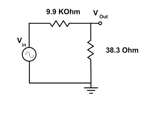
I had a problem with some of my measurements and then I decided to check experimental setup. I Used a small resistor (38.3Ω) in my circuit in series with signal generator and read its voltage for finding amount of current passed through circuit. But results weren't acceptable. So I put this resistor in a very simple circuit (attached pic) for testing my equipments (Probes, oscilloscope, resistors, ....).
I attached two oscilloscope probe tips to the Vin, and Vout. According to the oscilloscope manual, probe capacitance is 17pF in x10 mode. I got different values for output voltage, as written below, but I don't know what is the source of this problem. I think it is an acceptable assumption that resistor value doesn't change over frequency range. I'd appreciate it if anybody give me a hint.

@ 1MHz: Vin=18.4V Vout=73.6mV
@ 5MHz: Vin=18.4V Vout=108mV
@ 10MHz: Vin=18.4V Vout=182mV


I think it is an acceptable assumption that resistor value doesn't change over frequency range.
Yes, that's the question. An 38 ohm resistor can be almost constant up to GHz frequencies, if it's a suitable type. The other interesting question is, how you probe the voltage across the resistor, and if you can be sure, that you don't pick up unwanted signals by your probe's ground cabling.

The numbers suggest a large series inductance of the resistor (> 1 uH), like a wirewound power resistor would have.

P.S.: ALterantively a resistor parallel capacitance of a few pF would cause a similar frequency dependent error.
 

why dont you connect the probe ground to the circuit ground,make it a common ground.
and also give the same ground to function genrator
that might help:wink:
 

The other interesting question is, how you probe the voltage across the resistor, and if you can be sure, that you don't pick up unwanted signals by your probe's ground cabling.
why dont you connect the probe ground to the circuit ground,make it a common ground.
Tnx for reply. I connected probe alligator clips to the ground of the signal generator.
How can I be sure whether it picks up unwanted signal or not?
The numbers suggest a large series inductance of the resistor (> 1 uH), like a wirewound power resistor would have.
Is there any way to find out that this resistor is pure resistive or not with simple and common instruments, and how can I be sure that it is because of resistor?
 

Is there any way to find out that this resistor is pure resistive or not with simple and common instruments, and how can I be sure that it is because of resistor?
try making an impedence bridge that can verfiy if resistor is pure or not.
 

Run a sim with approximately 3 pF stray capacitance across the 9.9k ohm.
 
Last edited:

try making an impedence bridge that can verfiy if resistor is pure or not.
I think impedance bridge doesn't work here.
Run a sim with approximately 3 pF stray capacitance across the 9.9k ohm.
There are many different assumptions that we can make that may result in the same results but there are just assumptions. I think there is no way but using some devices like Impedance analyzer or some thing like this for testing resistors over frequency range.
 

I think there is no way but using some devices like Impedance analyzer or some thing like this for testing resistors over frequency range.
There are many things you can do.
- change from the unnsuitable 10k resistor to a more reasonable value that's less sensitive to stray capacitance. Or build the circuit in a way, that assures the stray capacitance to be below 0.1 pF
- also you can use a resistor type and probing technique (4-wire connection), that promises the series inductance to be neglectible for your frequency of interest.
 
  • Like
Reactions: Monady

    Monady

    Points: 2
    Helpful Answer Positive Rating
Status
Not open for further replies.

Similar threads

Part and Inventory Search

Welcome to EDABoard.com

Sponsor

Back
Top