Continue to Site

Welcome to EDAboard.com

Welcome to our site! EDAboard.com is an international Electronics Discussion Forum focused on EDA software, circuits, schematics, books, theory, papers, asic, pld, 8051, DSP, Network, RF, Analog Design, PCB, Service Manuals... and a whole lot more! To participate you need to register. Registration is free. Click here to register now.

[PIC] Power factor measurement using PIC18f4520

Status
Not open for further replies.
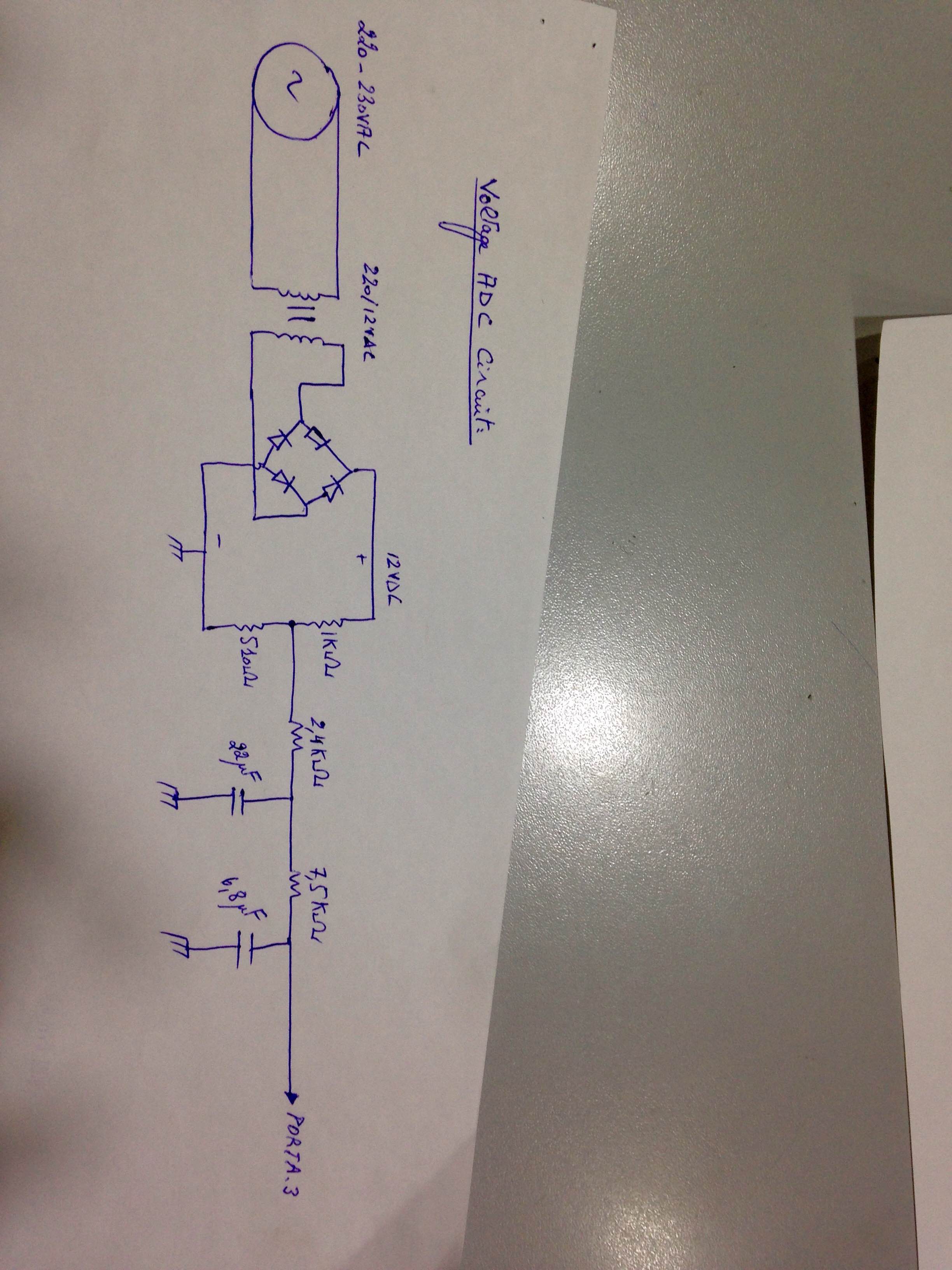
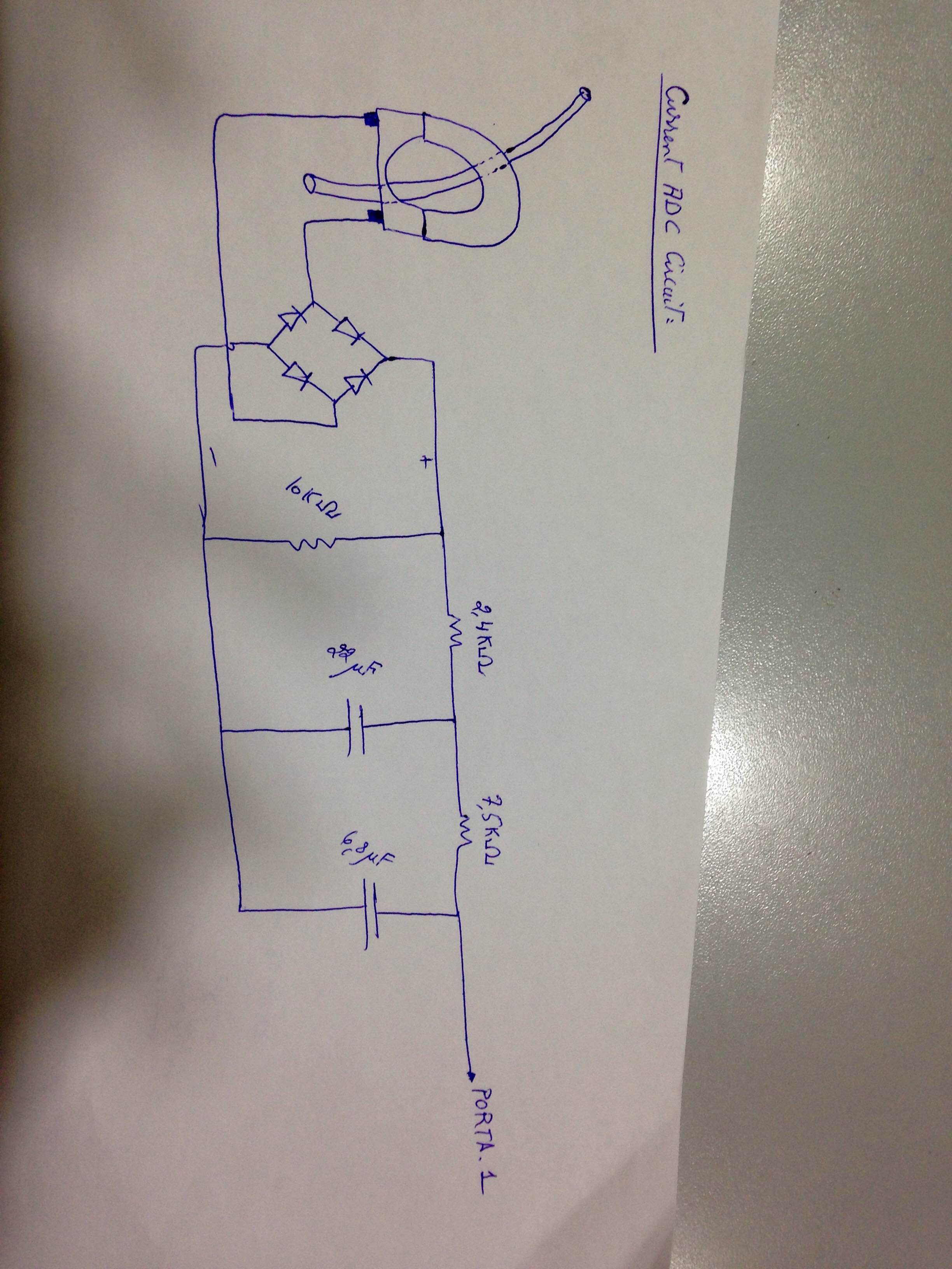
I have never done current measurement. I have only measured voltage using transformer and then the step down voltage into bridge then to capacitor and then to voltage divider to get 5V for 300V AC. I have measured this and displayed on LCD and 7 Segment Displays. I have done DC current measurement but with ACS712 Sensor.

ACS712 sensor can also measure Current but I have not used it to measure AC Current.

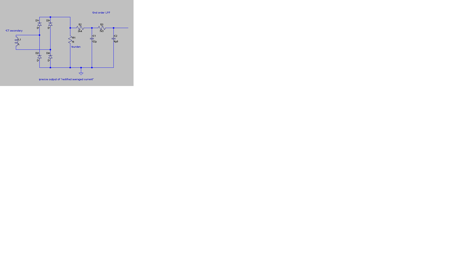
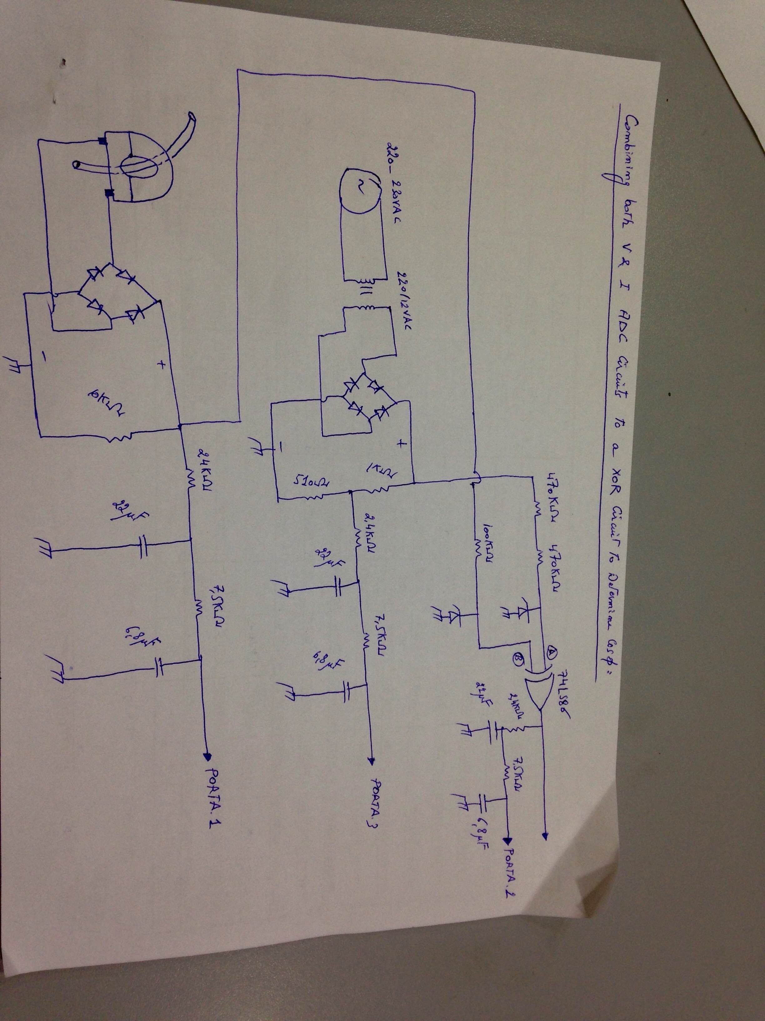
I have done the XOR method only in Proteus Simulation. The result was fluctuating between three values. For 0.707 it was displaying 0.704, 0.706, 0.711. Same with and without LPF.

I have not tested it in hardware. If you want you can test it in hardware. You can try both brian's and KlausST's methods. i am willing to write code for both their methods. If you are ready to build various circuits for V, I and PF measurement then I will give you different codes but you have to build the circuits first and provide me some data.
 

Hi,


No.
My preferred solution is to feed both AC signals I and U directely without rectifier and without filtering to the ADC. Nothing else. No XOR.

Inbetween i thought the digital pulse witdh measurement caused problems..and just remembered this alternatively could be done with an ADC.
...many ways...many solutions..maybe causes confusion...sorry.

Klaus

Hello,

So the CT circuit you've posted is following betwixt method not yours.

I tested it with 2nd order LPF, same as you posted it, with same res/cap values.

I've input its value to analog channel PORTA.1, 10 times, then divided the whole result by 10
I did
Code:
 Adcin 1,current
that is similar in C language to
Code:
ADC_READ(1)
No good results were on LCD, and even when load is disconnected, there still a "random" value that appears for I

Here is the BASIC code:
Code:
y = 0 //this is a single type variable
icounter = 10 //this is a variable used as a counter 

main: //main program loop

While icounter > 10  
 Adcin 1,current
 WaitMs 600
 y = y + current
 icounter = icounter - 1
 current = 0
Wend

y = y / 10 //since 10 accumulated results of ADC input value has taken place
y = y * 5 / 1024 //this is to return the input voltage, referred to current, to its analog value

According to your circuit, the analog value (y = y * 5 / 1024) must be for the 200W incandescent lamp, a 0.075 as seen on a DVM, but on the LCD it shows random value like:

0.007
0.105
0.03
etc...

Thank you
 

According to your circuit, the analog value (y = y * 5 / 1024) must be for the 200W incandescent lamp, a 0.075 as seen on a DVM, but on the LCD it shows random value like:

Whose circuit and what value ?

My circuit ? My code doesn't display ADC input voltage on LCD. My code displays voltage and current and according to my code for RA0 5V adc input is 300V AC and for RA1, 5V ADC input is 5A AC.

Some people say we have to do like this
Code:
adc_result = ADC_Read(0) * 5.0 / 1024.0;

For me for 5V ADC input ADC_Read(0) returns 1023.0 and so I always use

Code:
adc_result = ADC_Read(0) * 5.0 / 1023.0;

So, when adc input is 5V DC then ADC_Read(0) is 1023.0 and adc_result = 1023.0 * 5.0 / 1023.0 = 5.0.

I know for 0-1023 it is 1024 but using 1024 never gives correct result.


Build KlausST's circuits and for V measurement input 300V AC using a Variac and provide me the V DC you get at the adc input pin RA0. For I measurement use a 200W bulb as load and measure current using Multimeter and then provide me the dc voltage you get at the pin RA1. I will write a new code.
 
Last edited:

Hello,

I've tried this circuit:


The above is KlausST's CT circuit. I connected to it a 200W light bulb.
Using a DVM the output voltage of the CT circuit attached is 0.075V.

So when connected to PIC, and after ADC the result on LCD must show a 0.075
Instead, when made a
Code:
adc_result = ADC_Read(0) * 5.0 / 1023.0;
there wasn't a fixed value for V resulting from CT circuit, and the value changes such that sometimes it displays "0.105" sometime "0.007" sometime "0.031" etc..

- - - Updated - - -

Is the problem from the circuit itself, or code changes must be done? like increasing the icounter in order to sample more Adcin values?
 

Changes have to be made in the code but before that why don't you give the adc input voltage you get at RA1 when 200W bulb is connected ? Give the V DC you get at RA1 when 200W bulb is connected. I will make changes to the code and provide you new code. Test it and then tell whether it gives correct value or not.


Edit:

Burn the attached project and connect 200W bulb to Current measuring Circuit and measure the current using a Multimeter. Then provide the values for V and I displayed on LCD. Also build KlausST's V measuring circuit and input 300V AC to it. LCD will show values for V and I for 300V AC and current through 200W bulb. Post those results here. Use Auto Transformer (variac) to input 300V to V measuring circuit.
 
Last edited:

Hi,

@Khaled #183:

So the CT circuit you've posted is following betwixt method not yours.
Yes. I respect your decision not to go my way.
My CT circuit of post #172 (if I remember right) is just an improvement on the CT circuit before. More linearity especially with low currents, less ripple, fast response, less electronic parts.

No good results were on LCD, and even when load is disconnected, there still a "random" value that appears for I
From my experience and simulations the output voltage of my circuit should be very stable as long as the input is stable. It is well filtered, so there is no need to average multiple values.

But you see wrong results.
To debug it:
* check the voltage at the ADC input. With a scope if you have. It should be a straight, clean horizontal line, no movements. Or check it with a DVM to see if the voltage is stable. The ripple should be less than 4mV with stable input. Tell us the result. Value, and "is it stable?"
* if it is not stable we need to find the problem in the circuit.

* if it is stable, then change your program and show the raw ADC value on the display (0..1023), no average, no other calculation.

Tell us the results.
***


@pic.programmer #184:
Some people say we have to do like this
1024 is the correct value. But 1023 will introduce a minimal error, not of interest.


Good luck to both of you.

Klaus
 

Ok, so my anticipated load is of 8Amps as a maximum load.
from CT ratio: output current is 8/2000 = 0.004
For a burden of 10Kohms the output resultant voltage is 40V. This 40V can easily be voltage divided.
What are the values of the Resistor (other than the ground voltage dividing one) that helps protecting with help of Zener diode, that helps in protecting the ADC input in case of overloading?

That would work but I would be more inclied to use a burden that gives you nearer the voltage you want, maybe aiming at 10V for 8A load. It is a compromise, lowering the voltage intoduces more rectifier non-linearity and increasing it reduces the CT linearity. Using small schottky rectifiers (BAT85 for example) will help at low current measurment because the have lower forward voltage drop (~0.4V instead of the 0.6V for a normal silicon diode)

The ADC inputs should see an impedance of no more than about 5K. Inside the PIC is the multiplexer circuit that selects which input goes to the ADC then a sample and hold circuit that 'snapshots' the voltage while it is being measured. If the input impedance (= input series resistance in this case) is too high, there will be insufficient current to fully charge the holding capacitor and the result loses accuracy. The drawback to using a lower value is it makes the PIC input more prone to damage if too much voltage is put on it, such as if you draw too much AC current and the CT output is too high. I think I would use a value like 3.3K or 3.9K and follow it with a Zener diode of 4.7V or 5.1V rating which will protect the PIC and only have a marginal effect on the reading at the highest input voltage. As you will be normally working at a voltage lower than the Zener knee voltage it shouldn't have any effect on normal operation.

The method Klaus suggested a while ago was to do this, it is more accurate but more software intensive:
1. Bias two ADC inputs to half VDD (2.5V) and add the AC signals from the voltage and current sensors to them. (so they both swing 0V to 5V at AC peaks)
2. read the voltage ADC, if the voltage is 2.5V it must be half way between AC peaks so you are at zero crossing point so start a timer.
3. read the current ADC, if the voltage is 2.5V it must be half way between AC peaks so you are at zero crossing point so stop the timer and convert the count to phase shift
4. go back to step 2 until you have sampled the voltage enough times (ideally over several AC cycles)
5. multiple each set of samples to find instantaneous power V * I = W
6. find the peak reading in each set of samples to find the voltage and current.

It might be possible to do the zero crossing analysis on the captured samples rather than 'live' but the principle relies on taking many samples per AC cycle so the timing is far more critical and more storage memory is used. Even at 20MHz clock and using ADC 'end of conversion interrupts' I doubt the math could be completed fast enough to do it on each sample as it is taken.

Brian.
 
@ betwixt

So, Can I implement KlausST's method like this.

Bias RA0 and RA1 (for V and I measurement) at 2.5V DC. Then apply 2.5V AC to it. It will swing from 0 to 5V DC.

When RA0 is 2.5V start a timer of 20 ms (because I know mains frequency is 50 Hz) and take samples (200 samples in 20 ms)

When RA1 is 2.5V start another timer of 20 ms and take 200 samples.

Then find out the highest values of the two set of samples.

Multiply each set of the samples to find out apparent power.

How to find out true power ? By multiplying highest values of V and I samples ?


Edit

Should I use a PIC with two simulataneous ADC channels to take samples at the same time ?

How to find PF ? From Apparent power / True power ?
 
Last edited:

Hi,

@Brian:
I see a lot of confusion in ths thread. I feel very sorry for this.
The ADC inputs should see an impedance of no more than about 5K
I didn´t know.. From other microcontrollers they say 10k to cause an error less than 1LSB at full sampling speed. This is my error not to read the datasheet.
I don´t think this causes considerable errors.
If the OP ants this: I can adjust the part values.

The method Klaus suggested a while ago was to do this, it is more accurate but more software intensive:
No. My preferred solution is:
* Measure: True RMS U, true RMS I, true P_eff
* multiply true_RMS_U x true_RMS_I to get P_app
* divide P_eff / P_app to get cos(phi). finished.
* no zero cross detection/processing (neither HW nor SW), no rectifier, no analog averaging filter, no peak detection

Maybe the confusion was because I optimized the CT circuit. (After the OP decided to use it. But it never was part of MY preferred solution.)
And/or maybe because i suggested to use filters after the XOR and use ADC instead of digital capture.. because the capture cased a lot of troubles. (But also the XOR is not part of my preferred solution).

Again, I´m really sorry for this confusion.
I will respect the OP´s decision and support him to get good results.

Maybe the OP should start a new thread. This thread is too long now and nobody will go through all the posts to find out what hardware and software we discuss currently.
(It seems we all are confused, including me)

@KhaledOsmani:
Please start a new thread.
Please give all schematics you like to use. in your first post
Please give a summary of all the actual specifications, your targets, your decisions. in your first post.
So we all are able to focus on the actual problems. (leaving all the previously made discussions behind us.. let´s try a new start)

Klaus
 
I agree with Klaus and I'm sorry for mis-interpreting the method he proposed.

pic.programmer - the difference in effective power and apparent power is that one is the overall 'envelope' V * I and the other is the instantaneous V * I. The instantaneous takes into account that at the voltage and current measurements are sampled at the same (or almost the same) time and hence incorporates the shift between the waveforms. It follows that for good accuracy the ADC measurements themselves must not be skewed in time so with a multiplexed input single ADC the software must switch channels and measure as quickly as possible.

The 2.5V offset is to allow the negative part of the AC cycle to stay above 0V. The maximum AC voltage is 5V peak to peak but centered on 2.5V. No AC at all would be a steady 2.5V DC level.

Brian.
 
* Measure: True RMS U, true RMS I, true P_eff
* multiply true_RMS_U x true_RMS_I to get P_app
* divide P_eff / P_app to get cos(phi). finished.

I beg to differ.

true power is integral of V.I dt over one cycle (and multiply by frequency)

This is different from rms V . rms I; rms V (or I) is integral of V.V dt over one cycle and then square root of the result.

What is true rms? cos(phi) is defined only for sinusoidal waveforms.

P-app is also commonly called volt-amp (as expected).

What is true P-eff?

Confusion and more confusion.
 

Hi,

I agree.... confusion.

You refer to my words...this is my short form of what i described earlier in detail.

In the first line i described in short what happens on every ADC_interrupt, or better say "pair".
* the actual value of U is squared and added to the integral..to later calculate the true_RMS_value for U
* the same with I
* then multiply the actual value of U with the actual value of I and add it to the power integral...to later calculate effective power.

This was my first line...I don't want to describe the rest again. Your explanaition is correct..I wanted to do the same.

I write "true" whenever i calculate it according the definition. In opposite to the "estimation"of U_RMS via recifying and averaging the voltage. I call it "true" when the result is independent of waveform. The "averaging"method is not independent of waveform.

But indeed i wrote a mistake: I wrote "cos(phi)" but meant power factor. You are correct on this.

U_rms x I_rms = apparent power P_app.

Sorry. I tried to describe a long story short...it sems I failed.

Klaus
 

Hello all and thank you!

The following is the voltage measurement circuit:


The following is the current measurement circuit:


The result after ADC were 95% accurate, and stable. Yes KlausST What you've mentioned about this RC-RC circuit of making the system more stable is totally true. I've used them to Vadc and Iadc.

Now, I need to group these two ADC circuits, to a XOR circuit (74LS86) in order to make the analog input for phase. Following is the suggested circuit:


@betwixt I need you to confirm the XOR circuit if it is true or need more modifications, and also the flowchart of making the code for the phase angle determination in OshonSoft BASIC language, since both ADC for V and I are done with Oshonsoft regardless of its low simulation performance.

Please help me coding the XOR, also the flowchart of making the code if possible.

Awaiting replies, and comments about circuits
Thank you
 

Hi,

Good to hear that you are satisfied with the results so far.

...although addresed to Brian...a comment of mine:
About the XOR circuit I have concerns that the large 22uF capacitor may influence the circuit.
I think a simulation could clarify this.
I could make the simulation, if you want.

Klaus
 
The XOR circuit looks fine but you can omit one of the resistors at the 'A' input to the gate. The reason I suggested two was to increase their combined voltage rating when measuring diectly from the incoming AC line. With the transformer dropping the voltage you can replace them with a single 100K resistor.

For the output filter, the XOR frequency is also 100Hz so use the same values as the I and V connections.

The measurment method depends on whether you use the analog or digital method. Use one or the other, the result should be the same.

Digital:
You need to measure the duration of the pulse at the XOR output, the easiest way is to make it trigger an interrupt, start a timer, swap to monitoring the opposite edge trigger then stop the timer at the next interrupt. Essentially you are finding the leading and trailing edge of the pulse and counting 'ticks' between them. As the 'ticks' are at a constant rate (decided by the timer prescaler) you can convert the result directly to time.

Analog:
You measure the analog voltage from the filter. The voltage is proportional to the phase difference. Note that the highest voltage will be when the inputs are 90 degrees out of phase at which time the XOR output will be a square wave (see the XOR truth table) so it will average at 2.5V. If you want to, you can use a x2 voltage amplifier to utilize the full 5V range of of the ADC input or just accept it will be always be a little less accurate. You still get 512 steps of measurement for 90 degrees shift so the result should still be more than adequate.

You will probably have to add/subtract a small 'fudge factor' to the phase result, use a resistive load and find the difference from zero then use it to fix the result. This is quite legitimate and due to the phase shift introduced by the transformers themselves. Their shift will be constant so all you have to do is compensate for it in your results.

Klaus, the circuit is to find the average voltage of a unipolar waveform, 22uF will slow the resonse time to changes but shouldn't have any other adverse effects. The series resistor in the XOR output will protect it from overcurrent.

Brian.
 
Am I doing something wrong ? This is OP's Voltage Measurement Circuit.
 

Attachments

  • Voltage Measurement Circuit.png
    Voltage Measurement Circuit.png
    111.7 KB · Views: 79

The XOR circuit looks fine but you can omit one of the resistors at the 'A' input to the gate. The reason I suggested two was to increase their combined voltage rating when measuring diectly from the incoming AC line. With the transformer dropping the voltage you can replace them with a single 100K resistor.

For the output filter, the XOR frequency is also 100Hz so use the same values as the I and V connections.

The measurment method depends on whether you use the analog or digital method. Use one or the other, the result should be the same.

Digital:
You need to measure the duration of the pulse at the XOR output, the easiest way is to make it trigger an interrupt, start a timer, swap to monitoring the opposite edge trigger then stop the timer at the next interrupt. Essentially you are finding the leading and trailing edge of the pulse and counting 'ticks' between them. As the 'ticks' are at a constant rate (decided by the timer prescaler) you can convert the result directly to time.

Analog:
You measure the analog voltage from the filter. The voltage is proportional to the phase difference. Note that the highest voltage will be when the inputs are 90 degrees out of phase at which time the XOR output will be a square wave (see the XOR truth table) so it will average at 2.5V. If you want to, you can use a x2 voltage amplifier to utilize the full 5V range of of the ADC input or just accept it will be always be a little less accurate. You still get 512 steps of measurement for 90 degrees shift so the result should still be more than adequate.

You will probably have to add/subtract a small 'fudge factor' to the phase result, use a resistive load and find the difference from zero then use it to fix the result. This is quite legitimate and due to the phase shift introduced by the transformers themselves. Their shift will be constant so all you have to do is compensate for it in your results.

Klaus, the circuit is to find the average voltage of a unipolar waveform, 22uF will slow the resonse time to changes but shouldn't have any other adverse effects. The series resistor in the XOR output will protect it from overcurrent.

Brian.

Thank you Brian!

So i will replace both 470K to a single 100K.

This is the first time I interfere a code with your analog explanations.
Since it is not so critical it can be done with Oshonsoft.

Could you please provide me a sample so I can study it and try to achieive full code of output of XOR that images the phase angle?
 

Hi,

@Brian:
Klaus, the circuit is to find the average voltage of a unipolar waveform, 22uF will slow the resonse time to changes but shouldn't have any other adverse effects. The series resistor in the XOR output will protect it from overcurrent.
I should have described it more clearly: I meant the two 22uF in the voltage and current measurement path, not the 22uF at the XOR output. My concern is that residual DC voltage from the 22uF may affect the XOR inputs.

Klaus
 

Both your voltage and current measurement circuits are fine.

Suggestions for improvement: just replace the bridge rectifier with a low drop Schottky diode. A bridge rectifier drops two diode drops: for 12V it will be 1.2V (roughly; you have practically zero load) drop.

Also connect a 10K in series when you connect to the port. The ADC works best when it sees a small load (please check the manual). The ADC takes very little current and the capacitors will stay charged to the peak voltage (only load it sees is the voltage divider).

If you know that your line frequency is 50Hz and you take readings for 20 ms, you will cover exactly one cycle. You can directly calculate sigma (V^2); sigma (I^2) and sigma(V.I) and the power factor.
 
Added:
@pic.programmer.
I see nothing wrong in your circuit, but the voltage readings make no sense...

Klaus
 

Status
Not open for further replies.

Part and Inventory Search

Welcome to EDABoard.com

Sponsor

Back
Top